@bnsgeyer looks like the user would profit greatly from using the ArduPilot Methodic Configurator for Heli ![]()
@amilcarlucas how so? This is very unique guidance I am providing. I am still not sure how your tool is meant to work.
@kuspower here are the parameter changes
FILT1_NOTCH_FREQ, 7.5
FILT1_NOTCH_Q, 1.5
FILT1_NOTCH_ATT, 10
ATC_RAT_PIT_NEF, 1
ATC_RAT_PIT_NTF, 1
He is asking about parameters he could not find. I assumed he could not find them because they are not enabled yet.
The tool enables the parameters before using them, solving this problem.
If that does not apply here, ignore my comment.
@kuspower just read up on the filter. So you will have to set FILT1_TYPE to 1 and then reboot your controller before making the remaining parameter changes that I provided in my previous post.
Thank you so much Bill.
Also I setup 2 filters notchs, as they not filter the same datas.
I set FILT2 idem as FILT 1 for NEF
and FILT 2 for NTF.
Please finf below the logs for the sid to 15Hz with the RAT_PIT_P Pushed to 0,15 without oscillations.
00000055.BIN
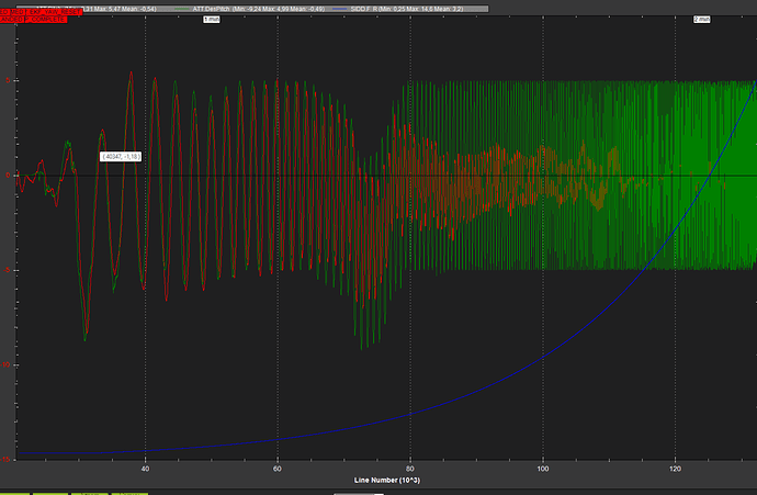
it’s seems to be beter now des att vs meas att:
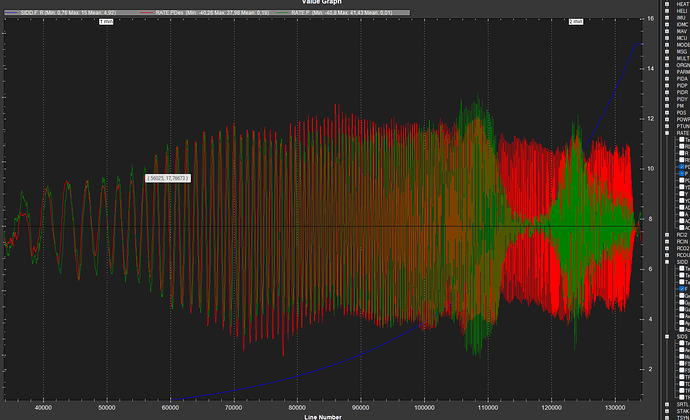
rate des vs rate meas:
however, the response for att fadeout continuously from 1hz…
Also good point is that we don’t overshoot anymore.
Do you think we can do better?
I will take a look as your log tonight but you are right that it does look like the notch removed the overshoot at high frequency
About the filter if I can set only one notch filter for the NEF and NTF, I set it as you told for the next tests.
Like this we can check if we can try to push more Rat_pit_D and Rat pit P and also Stab pit P.
thank you
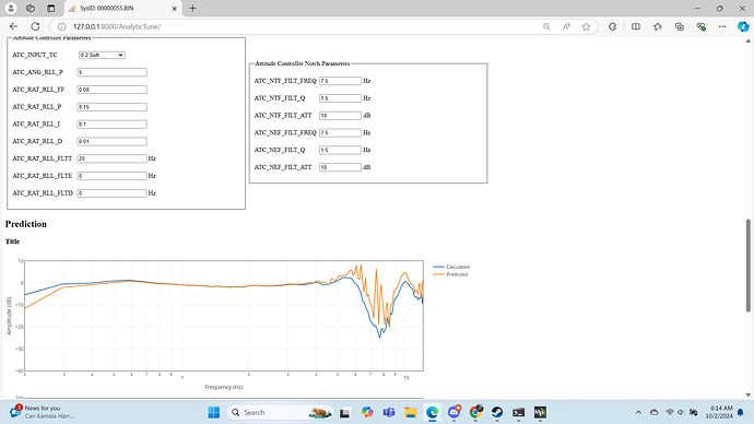
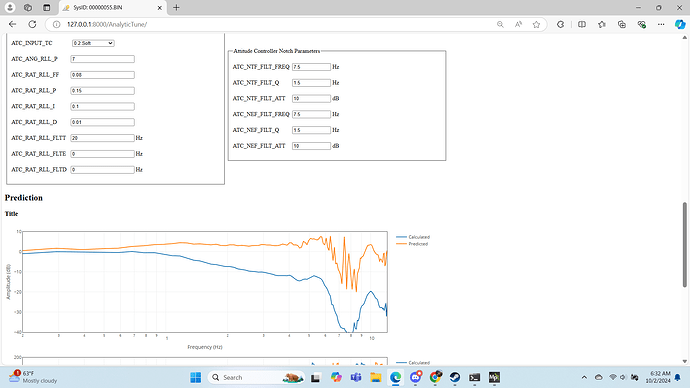
@kuspower Here is the plot of the rate controller comparison between calculated (actual) and predicted to show the accuracy of the prediction. Its pretty good but over predicts the peaks at high frequency. The x axis is frequency for the range where there is good coherence (data is reliable enough to make a prediction)
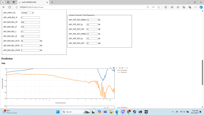
The next plot show the attitude controller but the plot for the calculated gain plot is of the attitude controller without the FF enabled feature. it is this way because I had you perform the sweep with SID_AXIS of 5 instead of SID_AXIS of 2. This was done because I didn’t want the ATC_ACCEL_P_MAX to affect the response. So you can see the predicted shows the gain slightly above 0 db for most of the frequencies up to 7 hz were there is a small hump up to 6 db.
lastly here is a plot of the gain for the response to your stick inputs. This includes the pilot feel parameter ATC_INPUT_TC but not the accel limiter. Again the plot of the calculated gain is not correct due to the SID_AXIS.
As for changes you could make to further improve, I think this is pretty good. You could raise the ATC_ANG_PIT_P to 6 or 7 but I would not go much above that. This is the attitude controller plot for ATC_ANG_PIT_P of 7
Hello Bill,
I,m really impressed by your tool, the result is awsome!!!
The uav feel responsive and safe now.
The prediction it calculate is really near the reality and permit to tune the uav limiting the risk and enhancing the final result.
I have also continuous yaw very slow oscillations around the target, there is also possible to try sid on it?
I keep you in touch with sid on pitch for stab P 7
Yes, that would be fine. Use the same settings for the pitch axis except change the SID_AXIS to 6 so it will sweep the yaw axis.
Hello Bill,
Attached you will find dataflash log with rat pit P @ 7, it’s perfect !!!
Also in the log there is the sid sweep for roll and yaw.
Roll seems good but yaw y tryed many things pushing/ lowering ff, p and D without success, like this is the best result I get with the standard pot tune process.
Maybe can you check the yaw sweep with your analytic tune ? Like this I can maybe make it perfect with your help ![]()
Hello Bill,
I want to be autonomous on my tune to not busy you, I re read you advices, to well understand the tune processus.
So, I retake the first sweep I sent you, and I used PID review tool, to try to see the same thing as if I have your analytic tune, but without the predictions:
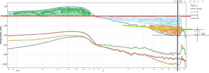
I plot the Error, with P D and FF, and I see the overshoot below 1 Hz, green zone:
I see that most gain commes from FF, so you advice me to reduce it.
Over 1hz to 7,5z there is a continuous increase in portion of non achieved rate.
At 8,5hz we see that there is a spike of less non achieved rate,
Due to this ponctual improvement, I draw the orange zone, that you call the hump, that is corrected by activating the pid notch filter centered in 7,5Hz. with Q @t 1,5 and 10dB attenuation, that we can see clearly on the plot. the 7,5hz and the 10db amplitude to filter, but how you determine Q ?
So after activating PID filter, increasing gain in P and D, reduce the non achieved rate in the 1Hz to 7,5hz band.
While without activating the PID Filter, increasing gain in P and D increase the non achieved rate in the 1Hz to 7,5hz band.
Hello Bill,
I check the sweep in roll axis:
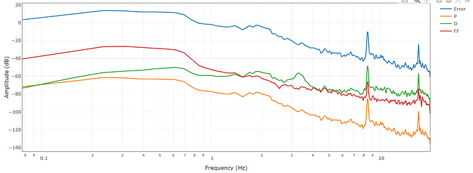
if I follow your explanation, I identify the error shape, si that it’s visualy linked to FF, so I reduce FF to decrese the overshoots beetwin 0,1 and 0,9Hz.
I try to put more rate p without modifying D
Increding stab P can flatten the low Hz range error.
did you see in this graph the need to use pid filter?
also as after 8 Hz nothing is useable, can we set low pass filter FLTE and FLTT to 8Hz ?
I appreciate that. And I’m sorry that I haven’t been as responsive. I am getting ready for the Developers Conference in just under 3 weeks. This tuning tool is one of the things I will be presenting at the conference. And hopefully it will be available to everyone soon after that.
Unfortunately, I don’t think this is the way to do it. This really only tells you half of the answer because it doesn’t tell you about the input. I suppose the error could indicate that but not in the same way. So I am not sure how useful this is. I will attempt to get you some analysis this week.
Hello Bill, I appreciate your help, I understand that this tool gives only partial indication.
In this case don’t lost time with the last logs.
I wait the end of week where normaly we don’t have wind to remake qualitative RPY sid for you analys later to help me.
About Analytic Tune, is pretty Good news, yes for sure all the community wait exited to have the chance to have this kind off tool to tune their uavs perfectly.
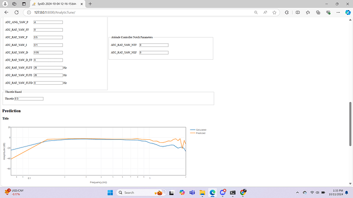
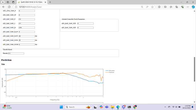
@kuspower I looked at the yaw axis. Here is the set up that I determined would work best.
Rate Controller
Attitude Controller
Have you tested rate P and D gains that I have shown in my graphs. If you have and there was oscillation then let me know
Otherwise you can follow this process.
The first thing to modify would be the ATC_RAT_YAW_FF. Set that to zero first. Then start increasing the RATE P and D gains. I might suggest bring up the rate D gain first and then raising the rate P gain to the value in the pics. I also lowered the Rate I gain and the Angle P gain.
If that all looks good then conduct a System ID run for the Yaw axis except use SID_AXIS of 3
Hello Bill, thank you so much I will try that asap and i will send you the sid log with sid axis to 3.
