In-Line resistor instead of Pull-up resistor on hot-shoe - prevents ISR flood - potential problems?

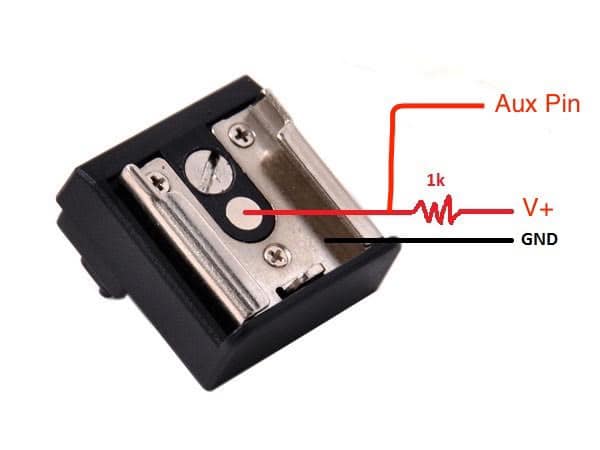
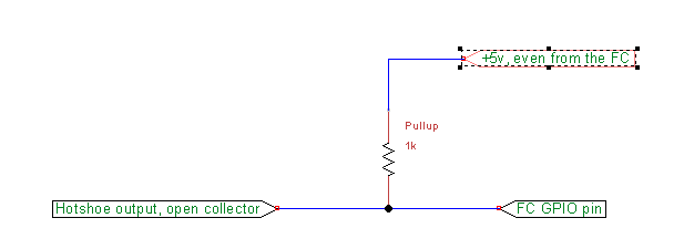
Earlier this week while I was sorting out a hot-shoe configuration I learned from @iampete and @tridge about the possible need for either a pull-up or pull-down resistor to prevent GPIO “float” that triggers an ISR flood - which could potentially cause the ArduPilot firmware to crash.

I fabricated and implemented a pull-up resistor that worked - but only temporarily.


For some strange reason that I’ve yet to figure out - the day after implementing the pull-up resistor it stopped working and the ISR flood condition resumed.

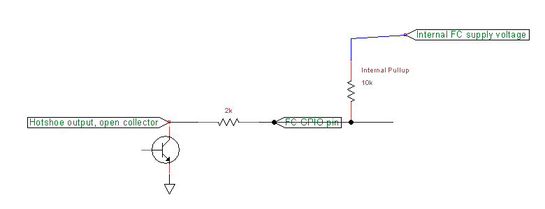
I decided to do some diagnostic work with my volt-ohm multi-meter. The camera’s manual recommended setting CAM_RELAY_ON=0 (low) to trigger the camera. So I elected to set RELAY_DEFAULT=1 (high).

Setting RELAY_DEFAULT=1 put a positive 3.5V on all the active GPIO pins - including the one I’d designated for hot-shoe input. So the hot-shoe signal was opposing this voltage on the pin.

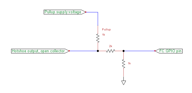
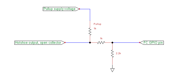
I decided to reverse the triggering - defaulting the GIPO’s to LOW and triggering the shutter using the GPIO relay on HI so the hot-shoe input signal wasn’t working against the GPIO’s 3.5V. Using my multi-meter inline between the hot-shoe and GPIO pin to measure the voltage presented by the hot-shoe, the hot-shoe function began to work again.

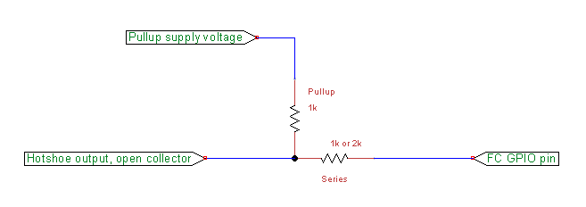
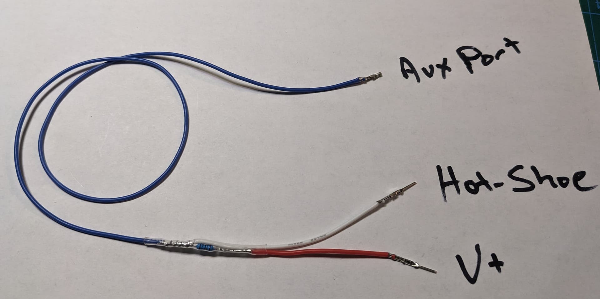
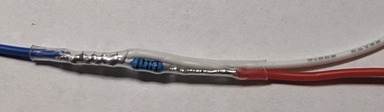
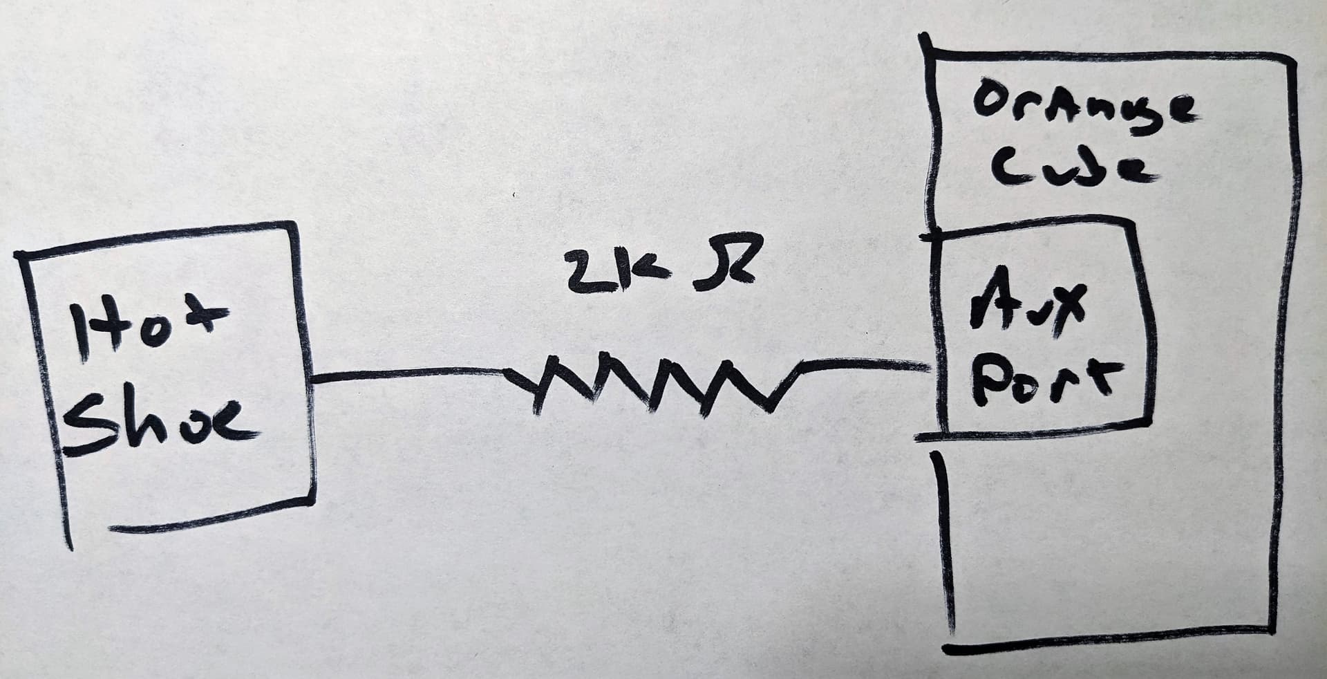
Removing the multi-meter and directly connecting the hot-shoe to the GPIO pin caused the ISR flood problem. But inserting an in-line resistor instead of the multi-meter - the hot-shoe worked properly.

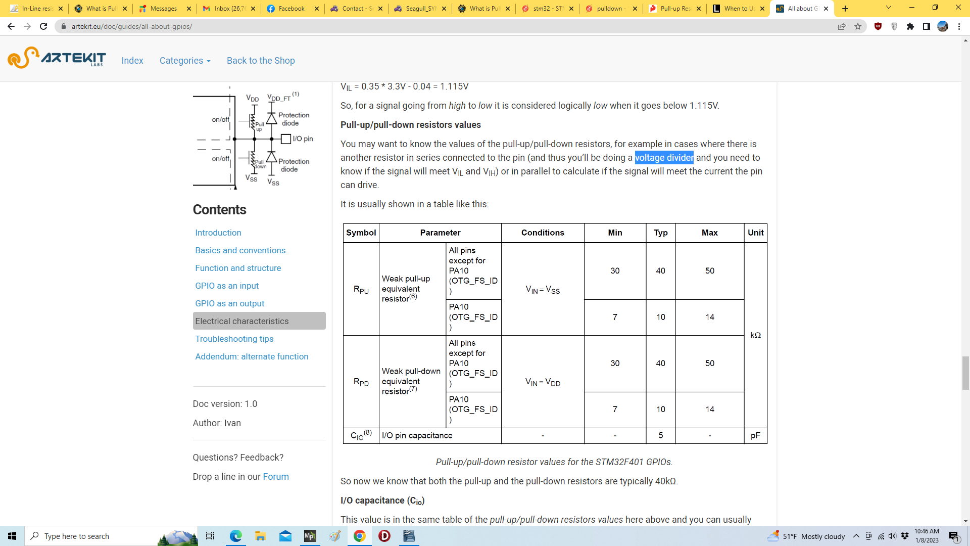
I started with a 1K ohm resistor, but found that a 2K ohm value worked as well - so I opted for that. 5K and 10K values did not work.

I was unfamiliar with pull-up and pull-down resistors - and I now have a working in-line resistor that may also have a name.

My question is - since an ISR Flood can be catastrophic, how safe might it be to fly with this in-line resistor? I may have well over a thousand images reported on the hot-shoe in a single flight.

Thank you for any thoughts or advice.

ISR Flood is no longer catastrophic since we ping the error and disable the input pin. It could be before we implemented the detection and disabling. However as the prevention is just to disable the pin the you need to fix it to get proper functionality.

1 Like

Thanks Pete - I appreciate your help with this.

My “in-line” resistor appears to work - at least on the bench. But as a novice, I have no idea if my in-line resistor opens up some other can of worms.

At least now it seems there’s less chance of the copter falling out of the sky from a GPIO problem,

Thanks!

What you have now is an internal pull-down scheme (assuming there is a resistor that can be activated by the onboard microcontroller) and an inline current limiting resistor.

The external pull-up was probably superior.

Thanks Yuri -

Agreed - I was sure more comfortable with the pull-up resistor that was working for about 24 hours. It’s pretty uncomfortable that it stopped working - especially not knowing the reason.

The fly in the ointment may be that because of the recommended settings for the relay to operate the shutter, the GPIO signal pin for the hot-shoe is HIGH - there is 3.5 volts present on the hot-shoe GPIO signal pin before anything is connected to it.

I’ve asked for verification - but it seems that Ardupilot requires all GPIO to start at boot-up at the same level.

I was also really surprised that there’s so little in the wiki about these issues. Another user offered me this diagram that he thought came from an earlier Ardupilot wiki:

ardupilot wiki pull-up drawing

This kind of information may still be in the wiki - but I’ve not been able to find it.

While hot-shoe input to the FC is an excellent feature - I have the feeling it’s not used much any more. I think people using a hot-shoe are more likely to connect the hot-shoe signal to some other device such as an Emlid M2.

One detail that I’ve thought of is that the camera runs on 8.4V, and that’s the voltage presented on the hot-shoe signal. My guess is that the FC is expecting something more along the lines of 5V - a more common voltage for cameras.

Lastly - the internals of my camera (Foxtech Map-02) is a Sony A5100. This camera does not have a hot-shoe. FoxTech has created one by tapping into the internals - and I have no way of knowing if it operates the same way as other camera’s hot-shoes.

I don’t know if any of these factors make any difference at all. And thankfully, ArduPilot firmware now disables a GPIO pin where an ISR flood occurs - reducing or eliminate the chance of the Ardupilot firmware crashing.

I’ll keep experimenting with the help of my gracious technical volunteers such as yourself - and report back for the aid of others facing this challenge in the future.

If the output voltage is 8V you can use a series resistor followed by the pull up resistor.

Just make sure the series is bigger than the pull up

Amilcarlucas -

I’ve had to brush up on board-level electronics as I’ve worked through this.

From what I’ve read the “series resistor” that is presently working successfully for me is functioning as a “voltage divider”.

I’ve learned that many microcontrollers such as the STM32xx have built in “weak” pull-up resistors. And that a series resistor that reduces the voltage reaching the GPIO pin may be all that’s required.

However sometimes - external pull-up - or pull-down - resistors are required.

On my workbench, my hot-shoe input signal seems to be working well with a 2K ohm series resistor - functioning as voltage divider.

I was glad to find an array of articles on-line that have helped me sort some of this out. One in particular addressed this: All about GPIOs | Artekit Labs Tutorials

I appreciate your taking the time to help me out with this.

1 Like

It’s only a divider because the input pin has some level of impedance and resistance to ground.
I think a pullup by itself would be OK if the supply voltage for the pullup was about +5 volts DC.
If you’re using a higher voltage for the supply, a series resister between the pullup and the flight controller input will help limit the voltage on the pin, but still not be a true “divider”.

The hotshoe output is a “open collector” which just connects to ground (0volts) and will not have a “supply voltage” of its own. It needs the pullup resistor and voltage (current) for

  1. the transistor to operate correctly
  2. there be some voltage level change for another device (the flight controller) to detect a changing signal (eg high to low)

Technically the open collector output doesnt need the pullup supply to be the same supply as the camera. It could be +5v from some other source, or even as low as +3.3v but that’s going to depend on the characteristics of the specific transistor. Then you probably would only need the pullup resistor.
The pullup resistor needs to be chosen so the transistor actually operates reliably.
image

So the first circuit here might be OK, maybe more reliable than just a pullup or just a series resistor.
The value of the series resistor is probably not critical, the FC input will have some input shaping and protection. EDIT: 4.7k might be better for the series resistor, just to limit damage but this circuit is not ideal
image

And this circuit includes the pullup plus a divider network that assumes you have probably got up to about 10 volts on the pullup supply. Change the divider values if you change the supply voltage.
Another Edit: swap the 2k and 1k divider resistors in this diagram
image

Let us know which is more reliable if you get to test them.

1 Like

This is better, for about a 9 or 10 volt supply voltage you get about a 5volt swing on the flight controller input.
image

1 Like

Shawn - You’re very kind to have provided such an informative response to this thread - thank you.

Taking a step back - it seems odd to me that something that should be relatively “plug and play” requires delving into this level of electronics detail. I have however, really appreciated and enjoyed the opportunity to learn more about GPIO’s and their implementation.

As a comparison, if you take a look at the documentation for the Seagull @Sync2, a device that attaches to a camera’s hot shoe and has connections for the Aux port - it describes the “plug and play” implementation I was expecting with the Map-02. And Seagull provides the necessary Ardupilot parameters - Foxtech does not.

The Foxtech Map-02 is a common camera - but has no documentation for the hot-shoe - as if it were designed to work in a “standard” manner. (Foxtech does provide some basic instruction for parameters for the Aux port relay function for the camera shutter)

My guess is that the hot-shoe lead on the Foxtech Map-02 camera is non-standard in some way. The Map-02 uses Sony a5100 internals - and that camera is not equipped with a hot-shoe. So Foxtech engineers have somehow added it. As a guess - they’ve implemented a hot-shoe signal that’s at a non-standard voltage.

And it’s really nice to know that Ardupilot firmware now has protection for GPIO input signals that could cause failures to the firmware.

I looked pretty hard on-line to find advice on connecting the Map-02 hot-shoe signal to the pixhawk Aux port - and found none. Another guess - I expect few people connect the Map-02 hot-shoe lead directly to an Aux port; Instead, a geotag devices such as the Emlid M2 is used - and maybe such devices are more tolerant.

I did install a pull-up resistor - and it worked for a few hours. I can’t explain why it stopped working.

The 2K ohm series resistor has worked reliably on the workbench - I’ll test it on a mission in the next day or two. I’ll need to verify that it’s successful operating on missions that have well over 1,000 shutter operations.

My issue is that by implementing an undocumented modification that I’ve introduced some other electrical problem that will fail in the end. Worse yet - cause the Ardupilot firmware to fail. That’s why I’ve taken the time to lean more about these GPIO concepts.

The ability to use a hot-shoe signal directly connected to an Aux port and use the Mission Planner geotag utility is a really great feature - especially since I’ve gone to the trouble of setting the copter up for proper RTK navigation. Using these native Ardupilot and Aux port features both saves the expense of extra geotagging hardware - but should increase reliability by reducing the number of points of failure.

In my research I’ve learned that STM32xx microcontrollers have “weak” pull-up resistors on GPIO pins. That may be why “standard” hot-shoe devices work without modification. And I expect there is also enough resistance so that my series resistor does create a voltage divider.

When I get it all sorted out - I’ll write a technical article for the benefit of other ArduPilot/Cube users who plan to use the Map-02 camera. I just want to be sure of the electronics before doing so - so I don’t suggest a solution that has the potential of adverse effects that haven’t yet shown up on my testing.

I appreciate your input - and all the other volunteer contributions on this topic. Thank you.

I think the alternative and more “plug and play” version would be to connect the pullup resistor to 5 volts and that would be all you need.
The reason they use an open collector output is it can easily be connected to any other interface expecting any other voltage, so it’s like a generic level-shifter and output all in one.

And that final diagram I put there above, is the one least likely to allow damage to the flight controller. We can continue going overboard with protections, but it should be OK since the flight controllers already have some protection built in.

1 Like

I think you are saying you have this now, a 2k resistor in series, and relying on the internal pullup (about 10k from memory)

When I simulate that I get a good 5v (nearly) on the GPIO pin, but on hotshoe operation the voltage only just makes it down below 1volt. I guess that’s why you were talking about a voltage divider earlier - since that’s what it is. That may or may not be reliable.

EDIT
I still suspect this would work fine with a 1k pullup to +5v and probably nothing else required.

Yes - you understood correctly. I installed a 2K ohm resistor in the hot-shoe lead going to the Aux port.

I tried a 1K ohm resistor because that’s what I used for my pull-up resistor (when it was working) and stated with that. 1K worked.

I then tried higher values. 5K didn’t work - but 2K did.

I can’t say if 2K is any better than 1K. Both worked.

One interesting note - the Foxtech Map-02 operates at 8.4 volts. That’s why I suspect it’s hot-shoe lead may be a non-standard voltage.

That’s the beauty of a open collector output - there is no voltage, it just pulls to ground - you set the voltage with your pullup resistor to suit the input you have to feed.

That’s why I think this would work, but I dont have one to test myself unfortunately - sorry for making you the guinea pig
image

2 Likes

Hi @jstroup1986
How did you go with the hotshoe tests?
I’m interested to hear about the series resistor tests, and if you got a chance to try just the pullup resistor to +5v by itself.

Shawn -

I apologize for may late reply.

The 2K ohm series resistor is working well. I’ve flown several photo surveys with over 1,300 images each mission - and haven’t missed any geotags yet. On the work bench I also tried a 1K resistor - which worked. But I’ve not test flown that.

If indeed this series resistor is creating a voltage divider because of the resistance of the GPIO port, than using a 2K ohm resistor reduces the voltage more than the 1K. I didn’t take the time to measure this.

It’s quite possible that a pull up resistor with 5V would have worked. Interestingly, I reached out to Seagull to ask about the voltage required on their #Sync2 hot-shoe adapter. They require 3.3V.

As an novel suggestion, Martynas at Seagull suggested taking the 3.3V from the Spectrum connector and using it as the servo rail power for things like their #Sync2 hot-shoe adaptor. I suppose I could use it as a voltage for a pull up resistor too.

My copter only has 12V and 8.4V BEC’s in addition to the Mauch BEC for the flight controller. I really didn’t want to add another. As the 2K ohm series resistor seems to be working - for simplicity it may be best to just stick with that.

Thanks for replying Joseph.
I’m with the Seagull person - a 1k pullup resistor to 5v (or 3.3v, which is probably their minimum) obtained from the flight controller. The current draw through the pullup will be 5ma , not enough for an LED for example, so any flight controller will be able to safely handle that.

Thanks to help from kind people like you, I managed to work through it.

I’m guessing that there aren’t many people using Aux-Port/GPIO for inputs. But even so - I’d expect camera hot-shoe inputs might be fairly common. More so in the past before geotagging devices like the Emlid M2 were developed.

For folks who’ve worked with electronics at the board level, implementing a pull-up resistor might seem obvious. It made perfect sense to me once I understood the problem. But I was unlikely to figure it out without some guidance.

I was amazed at how little there was in this forum or others about this particular issue.

Anyway - I’m always alert for ways I can help others succeed. I’ll do my best to pass along what I’ve learned here to help others.