I have no idea how you’re arriving at those offset values, but they appear to be wildly incorrect.
Set the following (the MB params aren’t used for uBlox serial GPS):
GPS_MB1_TYPE,0
GPS_MB1_OFS_X,0
GPS_POS1_X,0
GPS_POS1_Y,0
GPS_POS1_Z,0
GPS_POS2_X,0.45
GPS_POS2_Y,0
GPS_POS2_Z,0
I’m assuming the Rover antenna is toward the front of the vehicle. You may want to measure again from center to center on the patch antennas and adjust that 0.45m value accordingly.
If GPS errors persist after correctly setting the autopilot parameters, connect each GPS module to u-Center one more time and use the little gear icon (the one with the red dot, right side of the image below) to reset each of them back to defaults. Then close u-Center and preferably never open it again.
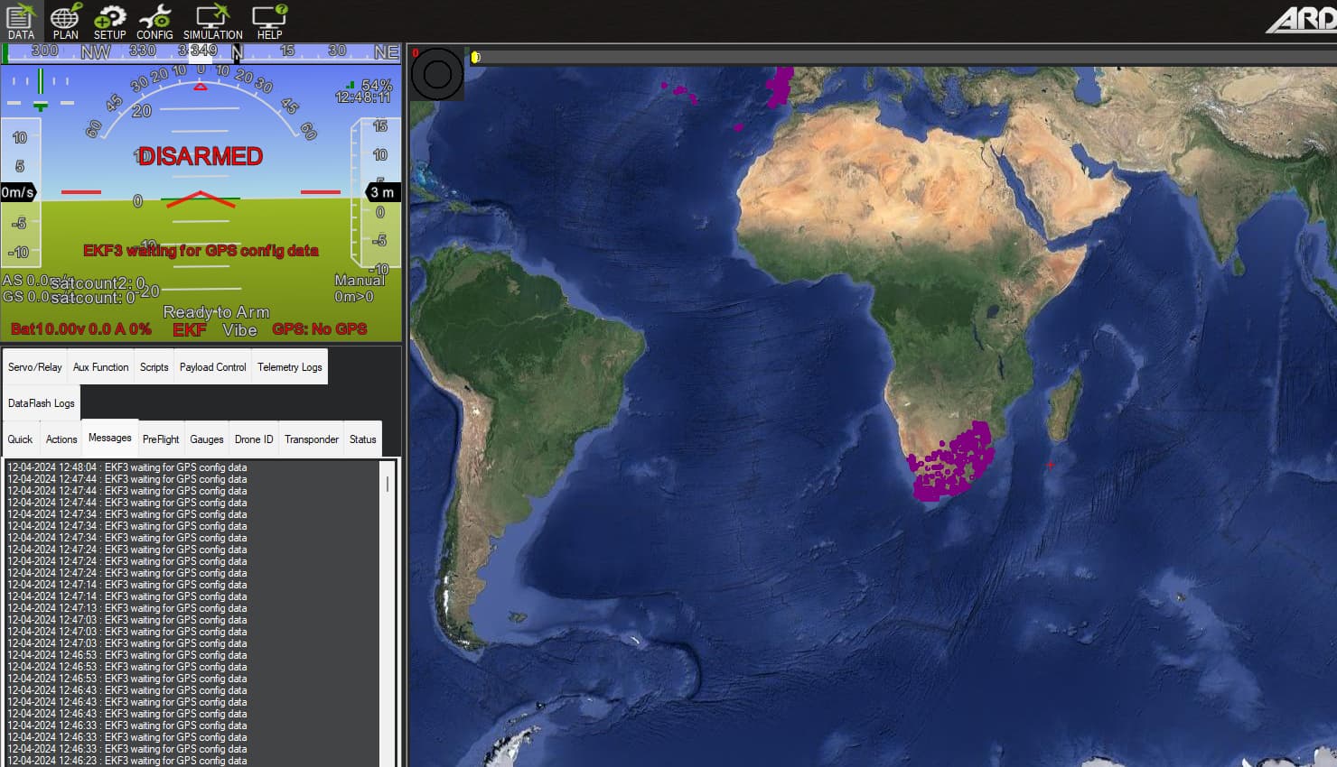
As you mentioned I changed the above parameters and reset the zed f9p’s to default configuration. Now GPS is not detected in the autopilot. I attached the param file and image for your reference.
Power cycle everything after making significant changes.
You reversed the order of GPS_TYPE and GPS_TYPE2 values. Making random changes will not help troubleshoot, though this isn’t the cause of the present issue. Recommend setting them back to 17 and 18, respectively.
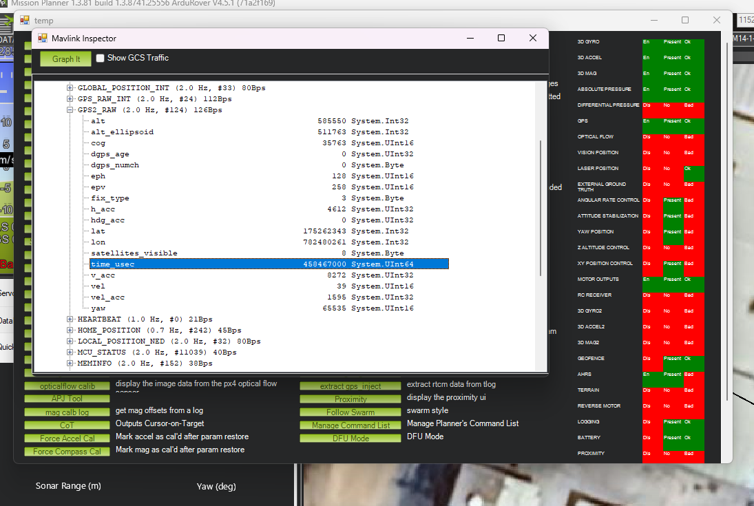
I tried many ways to get the yaw value from the zed f9p, but still, in the Mavlink inspector, I am getting the gps2_raw yaw value is 65534. I attached an image for your reference. And I am receiving continuous error messages like unhealthy AHRS or unhealthy GPS. Please help me to clear this issue.
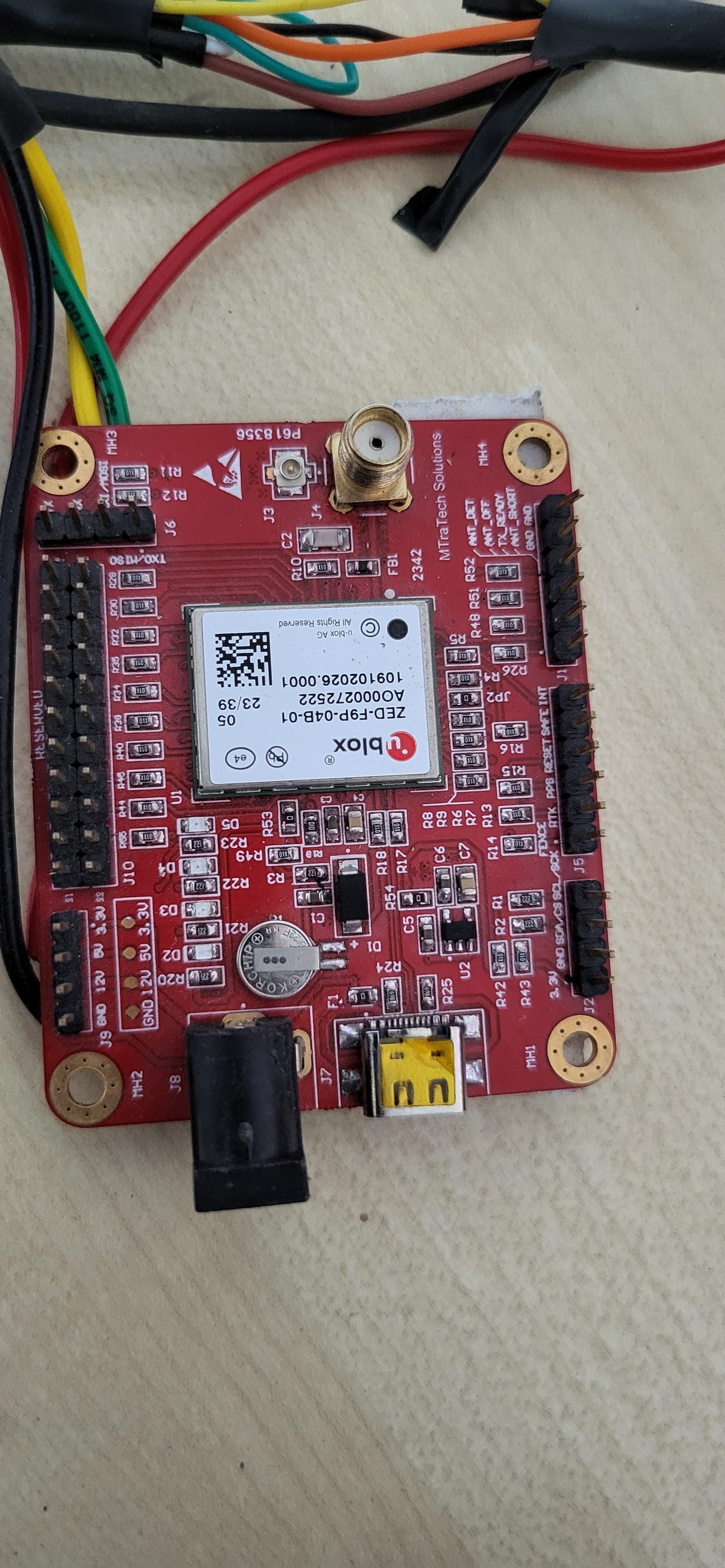
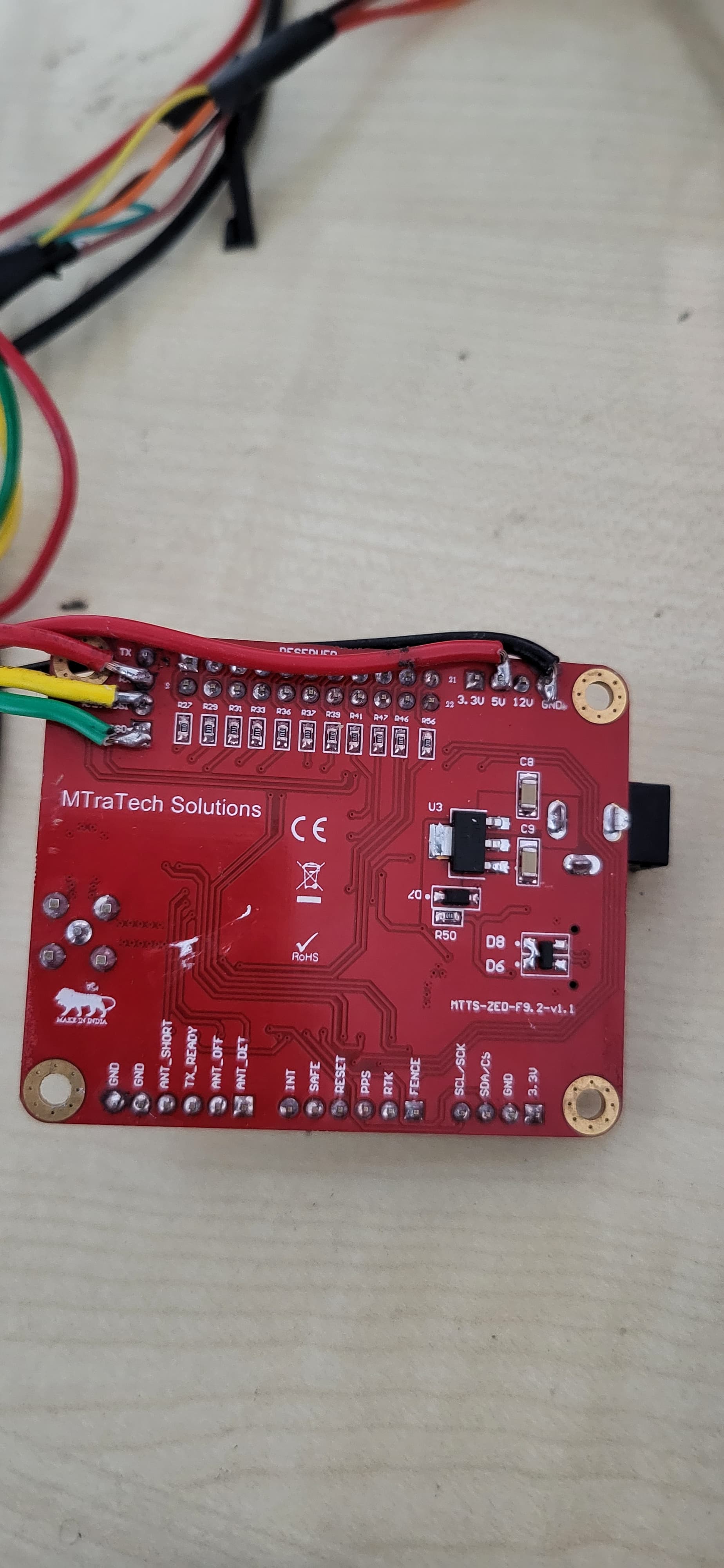
I am using the different zed f9p dev board, if I buy simplertk2b boards and configure them with the cube controller as per the below document, will it work? Please let me know. I attached images board images for your reference.
I purchased simplertk2b boards as per the suggestion. Now I am not able to receive any data from the rtk boards. In the mission planner, It shows no GPS. Please guide me on configuring the rtk boards and what parameters I need to change in the MP.
Hello @Yuri_Rage and @marblecreek,
I am now successfully receiving yaw values from the GPS2, and the RTK is fixed in the GPS2. Your continuous support and patience have been instrumental in reaching this milestone, and I am truly grateful.
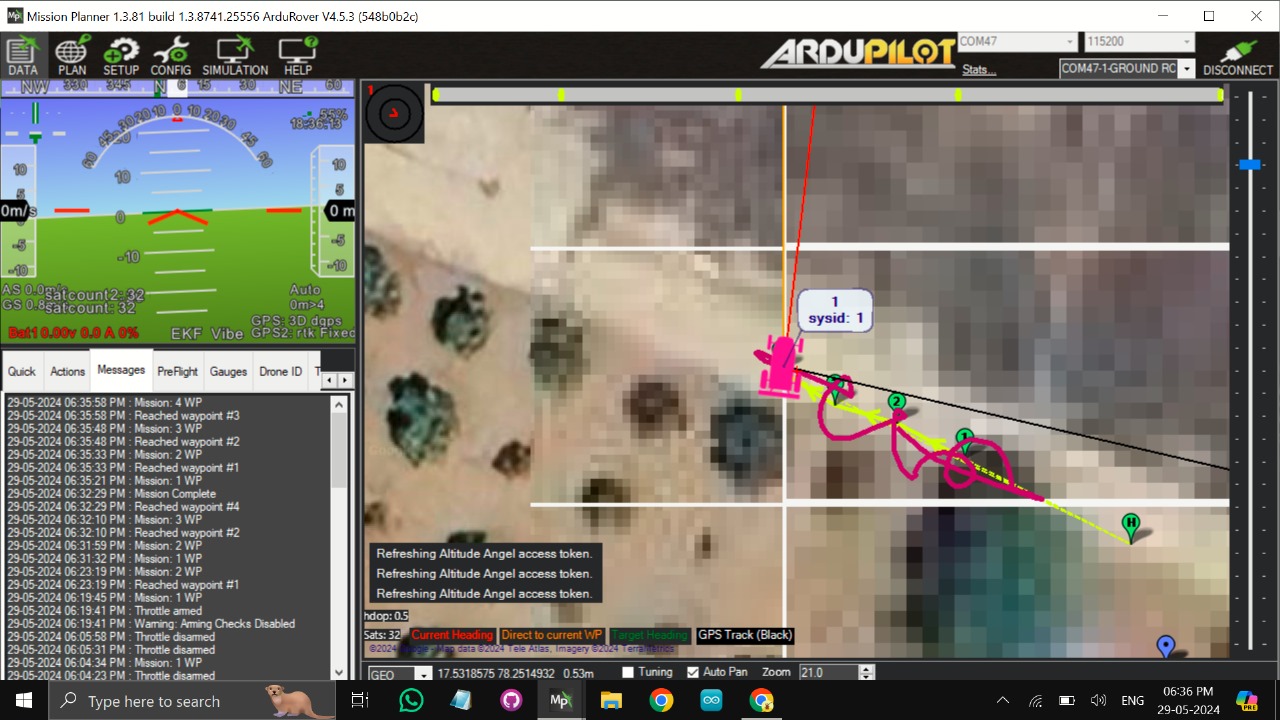
However, I am currently facing an issue with the position accuracy of the rover. Despite having RTK fixed, the rover is experiencing inaccuracies at every waypoint, resulting in multiple unwanted turns. I have attempted to rectify this by using an external RTK injection as well as operating without it, but both methods have yielded the same unsatisfactory results.
To help diagnose and resolve this issue, I have attached reference images, videos, and the parameter file used during these tests. Your expertise in reviewing these materials and providing guidance on how to achieve centimeter-level accuracy with precise heading would be invaluable.
I look forward to your advice and recommendations on how to improve the system’s performance.
Videos are nearly useless. Upload a .bin log, but only after you read and comply with the rest of this post.
You have arming checks disabled, which is almost always a bad idea.
Most of your parameters are at defaults, which means your vehicle is completely untuned. It knows where it is and where it should go, but it has no idea how to get there.
Follow this guide meticulously. Do not skip steps. If you have trouble, report back with a .bin log showing the outcome.
There aren’t enough underlines in the world to underscore what Yuri just said. He’s had to tell a ton of people the same thing. Best to do your part following the instructions as you’ll learn tons about the system, and in the end, will be a shorter path to a reliable system. And, others are more apt to help those that help themselves…
Following your suggestions, I am currently working on the first drive with the rover and have encountered some difficulties with the steering and throttle tuning. Initially, I attempted manual tuning, but it did not yield the desired results. Consequently, I ran the Rover QuickTune LUA script, but the rover is still not tuning properly.
For your reference, I have attached the BIN file and parameter file from the recent trials. Please analyze these files and provide insights on what changes are needed and what might have gone wrong.
Thank you for your continued support and expertise.
I’m writing to follow up on my previous message regarding the steering and throttle tuning issues I’m experiencing with the rover. I understand you may be busy, but I was wondering if you had a chance to review the log files I sent over. Any insights or advice you could provide would be greatly appreciated.
Thank you for your invaluable guidance regarding the controller adjustments. Following your instructions, I have successfully started receiving continuous yaw data.
However, I am currently facing challenges with the RTK base station setup for my agriculture application. My objective is to achieve a 5cm accuracy level for my rover. Unfortunately, I am encountering difficulties in maintaining a consistent RTK fixed state, especially for GPS2. Although I am transmitting RTK correction values through the ground control station via ZigBee telemetry, the RTK fixed state is achieved very rarely and is not consistent.
Could you please provide guidance on how to achieve the desired cm-level accuracy? Your continuous support has been instrumental in the progress of this project, and I greatly appreciate your assistance in overcoming these current challenges.
How long is the baseline between your rover and the RTCM base?
You have two GPS units on the rover. One of those GPS units should be in RTK-Fix and giving YAW (heading).
The other has two purposes - it supplies the YAW GPS with the RTCM corrections, and for my rovers, it also supplies the POSITION.
So without a third GPS, the fixed base or RTCM corrections from a third party, my position is only 3D, never Float or Fixed. I ignore the YAW GPS from a position factor because it is not as accurate as I’d like it to be. It is accurate relative to the second GPS on the rover, but that is not accurate enough to avoid hitting a post, nor repeatable enough.
When I start supplying corrections from a fixed base to the “position GPS” I start seeing Float and Fixed and the cm level accuracy you desire
Shorter baselines (between fixed base and the rover) are better - your accuracy can only be “so good” and every km of additional baseline distance adds additional inaccuracies to the position.
100km baseline is unlikely to get and hold FIXED and give you the accuracy you desire.
So - how long is your baseline?. What is the source of your corrections? Is it a dual band, triple band GPS?
Thank you for your previous explanation and support.
I am currently encountering an issue with my rover’s movement. I am using a local base station setup with a ZF9P module, antenna, and tripod, connected to the mission planner ground control station for corrections. After changing the telemetry, I am now able to achieve RTK fixed states on both GPS units.
My next step involves tuning the vehicle for smoother turns. When I set multiple waypoints in close proximity, the rover exhibits jerky behavior at each waypoint. I have attached the log for your reference.
Please note that the log file is quite large due to a battery disconnection issue that prevented us from shutting down the rover overnight. Kindly refer to the initial phase of the log for relevant data. I apologize for any inconvenience this may cause.
Could you please provide guidance on how to avoid this jerky behavior and achieve smoother transitions between waypoints?