I'm struggling to build a autonomous rover for college degree

So me and my team are new to the pixhawk world, it was recommended by a senior student so we’re still trying to learn the basics, however our project deadline is approaching.
I found a video that explains how to use the l298n H bridge to drive the motors via pix signals, however it didn’t work, where I’m from i couldn’t find a brushed ESC or a sabertooth as recommended by some topics, so we’re stuck, so we thought about using an Arduino to interface them but we couldn’t find enough data.
Also we’re not yet familiar with the pixhawk 2.4.8 numerous configurations and tests, and i can’t find a straight forward step by step guide, so what do i need to know and get while staying on budget.

Sorry if my topic is informal to the community and thank you.

1 Like

For the brushed ESC find one for a RC Car/Truck. Those are commonly available. Start with the 1st Time Setup Wiki:
Rover

1 Like

Can you provide a link to this video?

There are some really bad tutorial videos on YouTube. The Raspberry Pi Guy made a video claiming to show how to use a L298N h-bridge but people following the video ended up destroying their R Pi boards. I attempted to make a video showing how to use the L298N. It’s incredibly boring but I’m pretty sure it’s correct.

(Make sure to watch the end to see my Mecanum wheeled robot.)

As I show in the video, it’s helpful to control the h-bridge directly before trying to control it with a microcontroller. Here’s a link to the Parallax forum thread about this video.

1 Like

……….

There sure are.

Here’s the one i found about l298n

See this (essentially TTL glue to adapt Pixhawk DIR/PWM signals to the L298N bridge signals). I haven’t tried it, but plan to.

It is too simple, so may be that when changing direction some braking could be convenient. In that case you can try to insert an Arduino with the same idea.

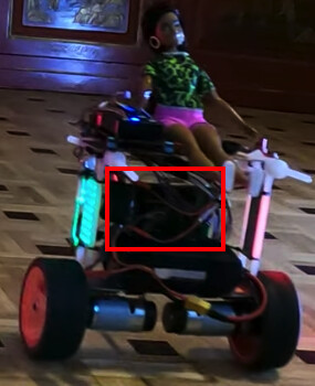
Here an Arduino adapts the SPEED/DIRECTION signals provided by the stepper motor encoders to the DIRECT/QUADRATURE signals required by the ArduRover software. It is hanging at the back of the driver and signals with red/green leds the QUADRATURE generated signals for the left/right wheels.

You can also use this other very simple board, soldering pulldowns as described. See it in action here (balance bot at the right).
image

Logic equations there are not valid: connecting Pixhawk1 PWM signals to L298N module INx’s doesn’t work since when its level is the same as corresponding other INx it would brake the motor.

So connect Pixhawk1 PWM (on MAIN’s) signals to L298N module EN1/EN2 signals, and Pixhawk1 DIR (AUX’s) signals to L298N module IN1/IN3. If you use the other four Pixhawk1 AUX’s for encoders there will not be available pins, so connect IN1/IN3 (Pixhawk1 DIR’s) to two external TTL inverters and connect the outputs to IN2/IN4. I have tried it and it works. So:

  • PWM’sEN1/EN2.
  • DIR’sIN1/IN3.
  • DIR’s inverted externally (TTL glue) → IN2/IN4.

This is the modification:


and this a video of a balance bot with it on a L298N: