Any one tried these i have some from a old project
WILL pixhawk I2C SDA & SCL handel 5+ volts pull-up resistors ?
I2C Communication
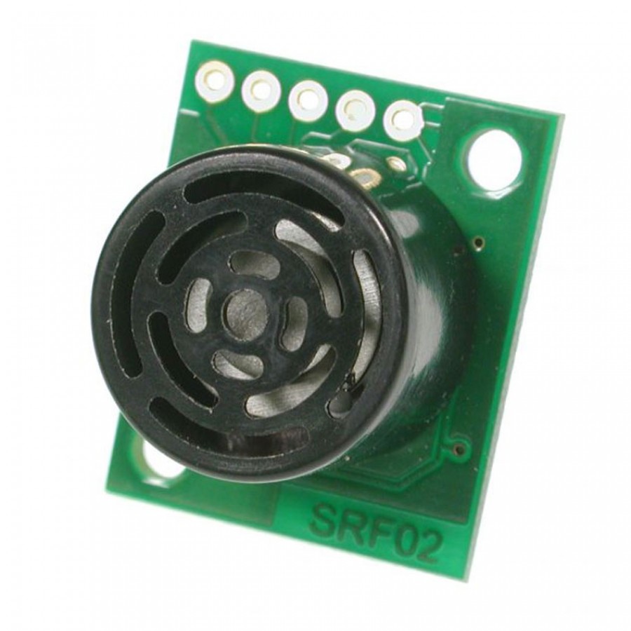
SRF02 Ultrasonic range finder
Technical Specification
I2C Mode
For Serial mode click here
To use the SRF02 in I2C mode, make sure nothing is connected to the mode pin, it must be left
unconnected.
The I2C bus is available on popular controllers such as the OOPic, Stamp BS2p, PicAxe etc. as well
as a wide variety of micro-controllers. To the programmer the SRF02 behaves in the same way as the
ubiquitous 24xx series EEPROM’s, except that the I2C address is different. The default shipped
address of the SRF02 is 0xE0. It can be changed by the user to any of 16 addresses E0, E2, E4, E6,
E8, EA, EC, EE, F0, F2, F4, F6, F8, FA, FC or FE, therefore up to 16 sonar’s can be used.
Connections
The connections to the SRF02 are identical to the SRF08 and SRF10 rangers. The “Mode” pin should be
left unconnected, it has an internal pull-up resistor. The SCL and SDA lines should each have a
pull-up resistor to +5v somewhere on the I2C bus. You only need one pair of resistors, not a pair
for every module. They are normally located with the bus master rather than the slaves. The SRF02
is always a slave - never a bus master. If you need them, I recommend 1.8k resistors. Some modules
such as the OOPic already have pull-up resistors and you do not need to add any more.
+5v SDA SCL
Mode GND