I am simply trying to spin a motor connected to an ADP ESC (120F3X) and a Pixhawk 6C Mini using Mission Planner, but not having any success.
The motor beeps once every 3 seconds, which means its “Waiting for signal tone, lower pitch”…
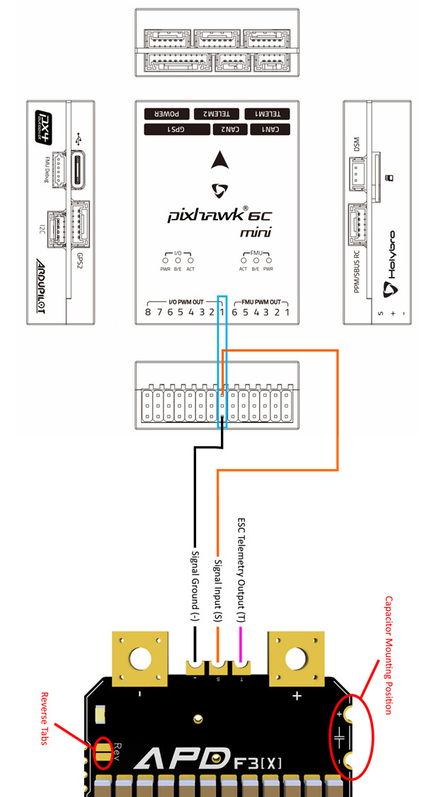
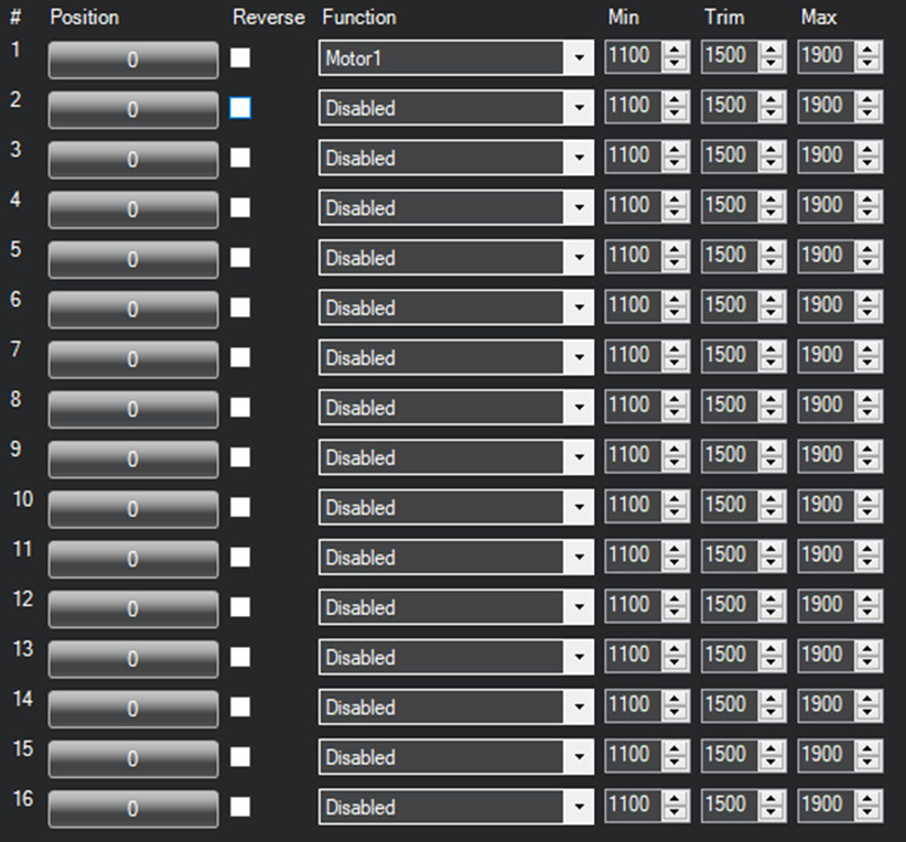
I have set position 1 function to ‘Motor 1’ in Mission Planner → Setup → Servo Output, but I have no idea how these positions relate to the Pixhawk (the Pixhawk only has 14 outputs where as Mission Planner shows 16 positions). The Pixhawk has the following outputs:
6 x “FMU PWM OUT”
8 x “I/O PWM OUT”
I tried connecting the ESC to each of the 14 outputs and even connected an oscilloscope to monitor the ‘S’ signal, but the Pixhawk is not sending anything.
I am trying to get it to work with PWM first, but then need to change it to DSHOT.
The Pixhawk is flashed with Copter V4.4.3 and Mission Planner is 1.3.8741.25556
The documentation for these devices is almost non existent, it seems like the only way to get these things to work is by posting on forums and hoping someone responds ?
Since you stated that you tried all pins I assumed that the problem must lie somewhere else. And this behaviour I’ve only observed with the safety switch. Are you sure that you didn’t connect the signal line to the ground pin?
I think that I/O should be the main ports. There are 16 ports in software since some boards support those. The difference between I/O and FMU is that FMU is the main processor, whilst I/O is runningonly the bare minimum of functions. With the concept that the drone should still fly with only the I/O Processor (don’t quote me on that).
Like I said, I dont know how the servo output position numbers relate to the headers on the Pixhawk.
I am connected to I/O PWM OUT 1, but I have also tried all the other 13 outputs too.
The only other connection on the Pixhawk is the USB-C connector, I assume I don’t need to provide additional power etc. on any other of the Pixhawk connectors ?
The servo output position one is set to function Motor 1, but I have no idea whether this relates to I/O PWM OUT 1 on the Pixhawk ?
I am using motor test in mission planner… but its not working as explained above !
Just a few things that aren’t covered:
Which output do I use on the Pixhawk and how does it relate to the 16 positions in mission planner ? e.g. is servo output position 1 = I/O PWM OUT 1 on the Pixhawk ?
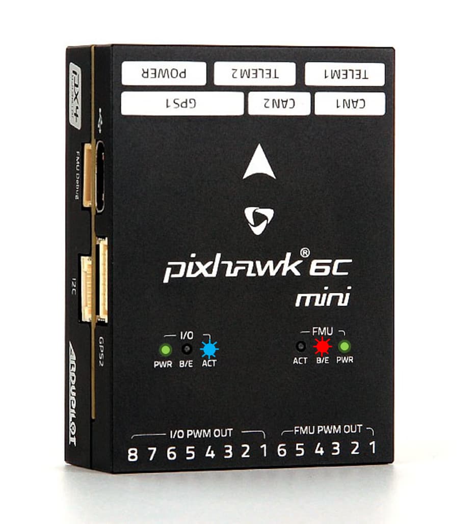
What do the status of the LEDs mean ? PWR is obvious, but what about the others ?
Assuming I get PWM working, I then need to change it to DSHOT. Where is the manual that explain how to do this ?
DSHOT runs at 1Hz, but I want it to run faster than this. How fast can it run and how do I change it ?
I’m sure there will be more questions as I proceed, but surely there should be a manual for all this ?
Can you show a screenshot of the messages screen?
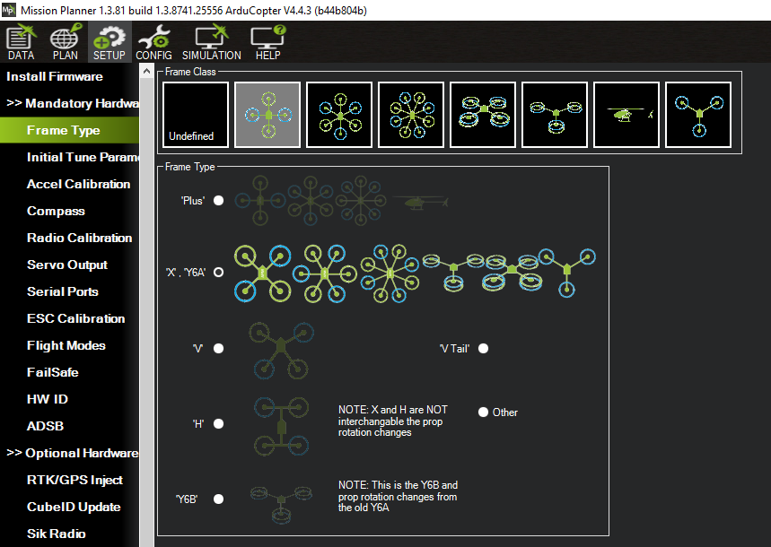
Unless the frame type is set correctly nothing works.
Also for a multirotor you will be better off using the FMU PWM OUT channels and DSHOT protocol instead of PWM. Those outputs are numbered SERVO9 onwards on parameters.
To use DSHOT set MOT_PWM_TYPE,6 and we can go from there once you get motors spinning.
Theres just one more thing I need to get working and thats the telemetry from the ESC
How do I configure the Pixhawk to request telemetry data ?
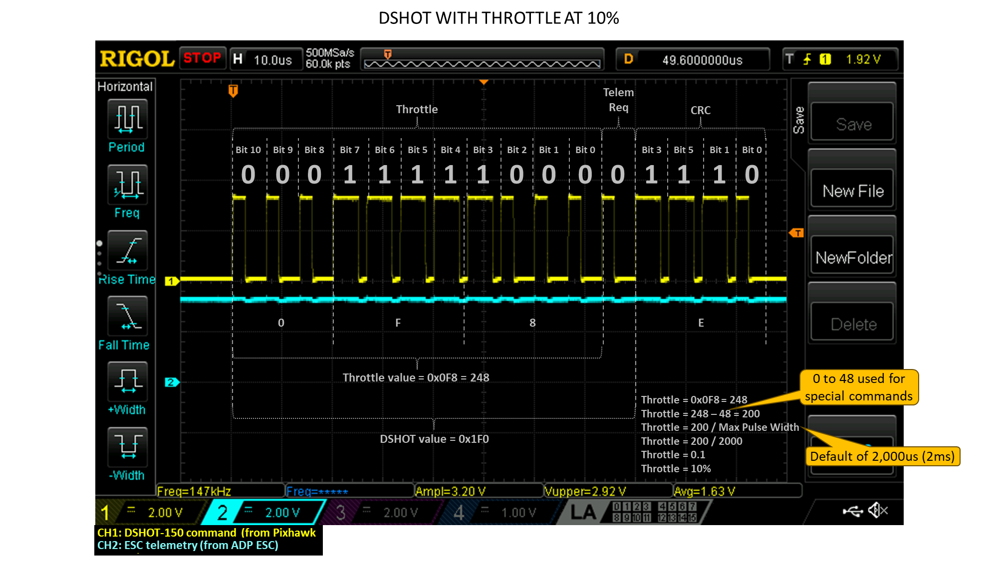
The 12th bit in the DSHOT command sent by the Pixhawk is the telemetry request flag but its a zero (low duty cycle). It needs to be a one (high duty cycle) in order to request telemetry data from the ESC
Check you messages tab for a line like: RCOut: PWM:1-8 DS600:9-14
There are two ways to get that sweet ESC data:
Bi-Directional DSHOT - a firmware change. This only gives you RPM though.
Connecting the telemetry terminal of all the ESCs into one combined wire and connecting to an RX pin of a serial port. This gives you all data, RPM, temperature, voltage, current…
Both can even be combined if you think RPM data is needed at a high rate but still want all the other data, for example small quads.
To get the data via serial port you need something like:
SERIAL4_BAUD,115
SERIAL4_OPTIONS,16 <- depends on FC
SERIAL4_PROTOCOL,16
I dont actually need the telemetry to be received by the Pixhawk as when I get the telemetry working I am going to write my own software (on an NXP development board) to decode the telemetry data. Therefore I don’t need to configure the Pixhawk UART.
But I don’t know how to configure the parameters to get DSHOT to request telemetry (there are nearly 1,000 parameters in Mission Planner!)
From the scope capture, you can see that the telemetry request bit is not being set to 1 in the DSHOT command…
My opinion is you would be better off using the flight controller to gather that data so it can use it, and the data could be forwarded on via another serial port (even USB).
Normal DSHOT operation requests the telemetry in the Ardupilot implementation, but I’m not aware of the actual commands to do so. We dont have on option to turn it on or off, except for rate: SERVO_BLH_TRATE,10
My opinion is you would be better off using the flight controller to gather that data so it can use it, and the data could be forwarded on via another serial port (even USB)
My task is to develop an independent data logger that runs separately to the flight controller, so this is not an option.
It turns out that you just need to set SERIALx_PROTOCOL to ‘ESC Telemetry’, that then causes the DSHOT message to request telemetry, so this is how you turn the telemetry request on or off.
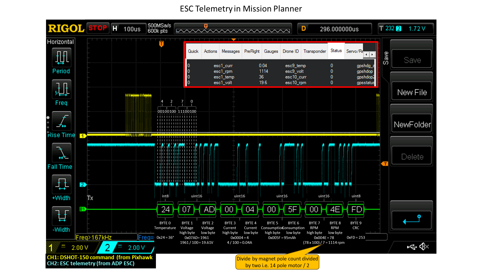
I’ve also realised that the ESC telemetry is not a DSHOT interface, it is in fact a UART interface…
I will be using the NXP UCANS32K146 development board (which uses the NXP S32K146 processor) to read the telemetry into a UART peripheral and then write the data to an SD card via SPI.