How to force GPS_YAW to rover's yaw? (simpleRTK2b+heading)

Hello there!
Last weeks, we have implemented some code to create a GPS_YAW with the Piksi modules from SwiftNavigation.
At the moment, we are having Fixed RTK and even a clean GPS_YAW! :slight_smile:
Could someone please help to see what setting I need to change to force our GPS_YAW to the Rovers yaw? Attached is the GPS status screenshot and our parameters.

In the screenshot you can see that our red Yaw status is always 360 degrees. The green GPS Yaw (241,17 degrees) is working fine when Iā€™m driving the rover.
The pink rover on the map is using the Yaw and not the GPS Yaw (always heading to the North of the map).


03-03-2022_gps yaw input working.param (16.4 KB)

messages tab:
3-3-2022 14:10:09 : IMU2: fast sampling enabled 9.0kHz/2.3kHz
3-3-2022 14:10:09 : IMU0: fast sampling enabled 8.0kHz/2.0kHz
3-3-2022 14:10:09 : RCOut: PWM:1-14
3-3-2022 14:10:09 : CUAV-X7 002F0018 33395119 31303534
3-3-2022 14:10:09 : ChibiOS: 93e6e03d
3-3-2022 14:10:09 : ArduRover V4.2.0-dev (cac75607)

1 Like

Hi @Koenstruction,

I think the issue is that the AP_GPS_SBP (or SBP2) GPS driver needs to be enhanced so that the yaw is consumed.

In particular I think it needs to fill in these three members:

float gps_yaw;              ///< GPS derived yaw information, if available (degrees)
uint32_t gps_yaw_time_ms;   ///< timestamp of last GPS yaw reading
bool  gps_yaw_configured;   ///< GPS is configured to provide yaw

Great catch! I was prepared to respond earlier, assuming a yaw source parameter inconsistency. When I couldnā€™t find one, I was stumped!

1 Like

Thanks guys!
@rmackay9, weā€™ve already integrated those variables into our code.

Since weā€™ve been trying for a few days to get it working, we now need some progress. This is why we have now temporarily changed our setup to simpleRTK2B Heading Kit. Thereā€™s a lot more documentation and questions about this online so we should get this working much soonerā€¦ :face_with_open_eyes_and_hand_over_mouth:

Today I got the GPS working but I canā€™t get the GPS status any better than GPS:3D FIXā€¦ I think this is also causing our GPS Yaw not working right nowā€¦ Am I doing something wrong? I set the ā€œBaseā€ configuration on our basic simpleRTK2B module, then I set the ā€œ10Hz simpleRTK2B (Rover)ā€ configuration on the rover simpleRTK2B module, then the ā€œ10Hz simpleRTK2B (Moving Base)ā€ on the same board after adding the simpleRTK2BLite module on top of it. After I saved all the settings on the boards and turned them off I added the (Long Range Europe) radios to the base and rover modules, do you know if we should program those radios too?
The rover module is connected to our ardupilot serial4 port with the pixhawk connector on the simpleRTK2B module and the antennas are >1.5m apart

The only setting I used in stead of the tutorial of ardusimple, is to swap GPS_TYPE and GPS_TYPE2 to 18 and 0 in stead of 0 and 18 (because now the GPS isnā€™t red but white in the display.

07-03-2022_gps input working but no rtk or correct heading.param (15.2 KB)

First, you canā€™t inject RTCM3 through MAVLink if your moving base is not connected to the flight controller. So, you will not achieve an RTK fix type on that GPS unless you are injecting it independently.

However, and confusingly, you should be seeing an RTK fix type in Mission Planner because the rover GPS that is connected to the flight controller should be getting RTCM3 corrections from the moving base (thatā€™s how yaw is determined accurately).

Unfortunately, I have little experience with the SimpleRTK2BLite, and I often recommend against using it with ArduPilot because of the inherent oddities with ArduSimpleā€™s recommended setup. I do have one to test, and perhaps I should get it out and do some experimentation to help folks like you.

It does appear that youā€™ve followed their instructions, although your choice to swap the GPS_TYPE parameters may be whatā€™s causing the issue. Typically, GPS yaw is seen on GPS2 in a uBlox F9P setup.

Lastly, make sure you have updated both boards to the latest 1.30 firmware from uBlox.

Hi @Yuri_Rage thank you for your quick reply,
I have mounted the simpleRTK2BLite module on top of my simpleRTK2B module, and on top of the Lite module is our radio. Do you think the Lite module doesnā€™t get RTK corrections with this setup?

I did start without swapping the GPS_TYPE parameters, but this also didnā€™t work so I thought it would be cleaner to use it swapped.

I will upgrade all boards to the latest firmware, until now I didnā€™t check the version so maybe this will help!

Well, I think what youā€™re doing should work, but I just canā€™t say for sure. I will do some experimentation here and get back to you soon.

In the meantime, you could connect the Lite board to the autopilot as GPS_TYPE=2 just to see if the RTCM3 is successful there.

Also, try the 5Hz config files. 10Hz updates to the flight controller can be too fast to be reliable.

Thanks so far! I will use the 5Hz files, and see if we get RTK with the lite module.
I have also asked ArduSimple for help, I will update here when they come back to me :slight_smile:

You may have to un-sandwich the boards to confirm the fix type of the Lite board if you want to connect it to the autopilot.

I did just get a moving baseline configuration to work on a Cube Orange using ArduPilotā€™s auto configuration by separating the boards and connecting the Lite (moving base) to SERIAL3 and the bigger board (rover) to SERIAL4. This is a more ā€œtypicalā€ configuration than the daughterboard setup that requires u-Center and ArduSimpleā€™s config files. It also allows you to monitor both GPS modules via MAVLink and avoids the red GPS display in Mission Planner. If you have a UART to spare, that might be preferable for you.

Iā€™m having some trouble uploading the config file to the Lite board via u-Center and an FTDI adapter, but I will keep trying to see if I can get the ArduSimple method to work.

Great work, thanks a lot @Yuri_Rage.
Iā€™m going to test this!

Let me try and explain another convoluted method that works and allows you to keep the boards sandwiched together in the end:

NOTE: I have made multiple edits in rapid succession to these instructions. During my last revision, I followed this exact procedure to get things working.

First, physically separate the boards and connect each to the autopilot by following the ArduPilot wiki instructions. Connect the moving base (small board) to the first UART in order, and the rover (big board) to the second. I used SERIAL3 and SERIAL4, respectively on a Cube Orange. Use the following settings in addition:

  • GPS_AUTO_CONFIG=1
  • GPS_SAVE_CFG=2
  • GPS_DRV_OPTIONS=0

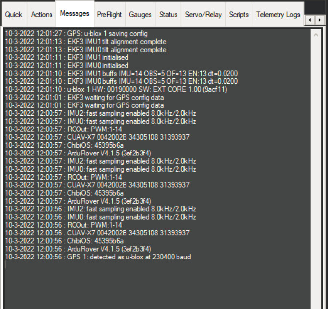
Power the autopilot on and let it auto configure both boards. Wait for these messages before continuing:

  • GPS: u-blox 1 saving config
  • GPS: u-blox 2 saving config

This way we know we are using ArduPilotā€™s latest recommended configurations on both boards.
Confirm that GPS yaw is operational in this configuration.

Power the autopilot off.

Sandwich the boards together, disconnect the moving base (smaller board) from the autopilotā€™s UART and apply power. Set the following:

  • SERIAL3_PROTOCOL=-1 (or the port where the moving base was previously connected)
  • GPS_TYPE=0
  • GPS_TYPE2=18
  • GPS_DRV_OPTIONS=1

Leave all other settings as previously configured.

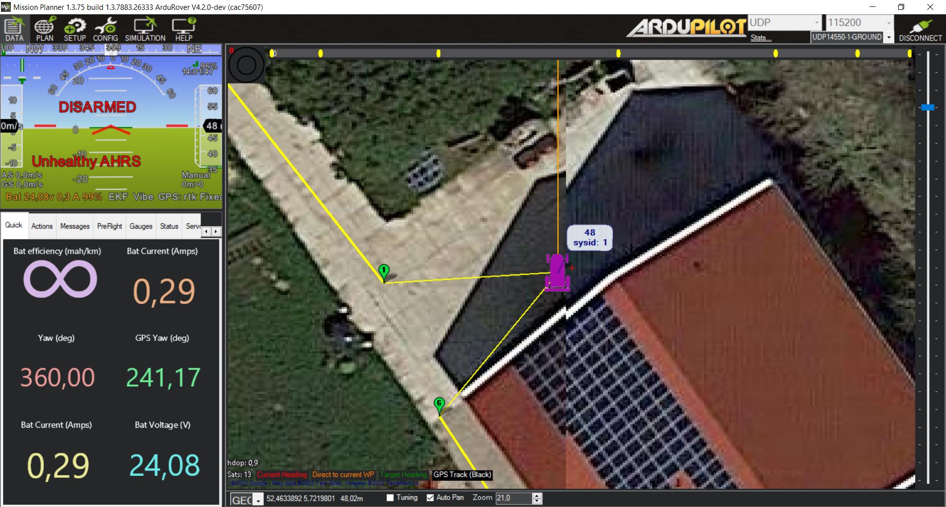
Cycle power again, and you should get yaw (with red GPS indications in MP because GPS1 is not present).

At this point, you can swap to:

  • GPS_TYPE=18
  • GPS_TYPE2=0

Reboot again to eliminate the red GPS indications and warnings in Mission Planner. I have confirmed that this works, but wait until this point in my rather unorthodox instructions to do so (to avoid accidental reconfiguration of the rover). Cycle autopilot power and restart Mission Planner after making this change.

In this configuration, you should be able to inject RTCM3 to the moving base via the radio connections on the Lite (smaller) board. However, you cannot monitor it via the autopilot. The only connected GPS should almost always show RTK Fixed because it is the rover GPS receiving RTCM3 from the now disconnected moving base.

I certainly understand the confusion that might ensue by trying to follow these instructions, but you can avoid using u-Center other than to update the firmware, and the configuration that results should be very stable and compatible with ArduPilot.

2 Likes

I wanted to try one more thing before calling it a day - itā€™s a little goofy, and probably an unnecessary tangent to the problem at hand, but it does work.

The bigger board exposes UART2 the RX/TX pins of the Xbee female header.

The Lite/smaller board exposes UART1 on the XBee male (bottom) pins and UART2 on the XBee female (top) pins.

Since the autopilot uses UART1 for its communication, you cannot connect the moving base (Lite board) to the autopilot when the two boards are mated - it causes serial conflicts.

However, if you flip the Lite board over, you can connect these pins as shown and set GPS_DRV_OPTIONS=1 to allow direct comms between the two boards on UART2. The ground and 3v3 pins arenā€™t strictly necessary, but they hurt nothing and helped stabilize my precarious setup. The key is to connect the Lite boardā€™s TX pin to the bigger boardā€™s RX pin.

In this way, you can connect both boards to the autopilot and continue to offload the base to rover RTCM3 injection to the F9P modules directly.

I canā€™t say I recommend putting this on a vehicle - it was just a proof of concept. But with a simple adapter board that criss-crosses the UART2 pins, you could still mate the two boards together for space savings, with the Lite board upside down on top. Of course, this would make using the XBee radio module somewhat difficultā€¦

Back on topic, I have an XBee USB adapter on order to try and overcome the FTDI issues Iā€™m having and then can fully test the ArduSimple instructions.

1 Like

Today we made it! The gps yaw works! Thanks to your explanation @Yuri_Rage :pray:t2::muscle:t2::+1:t2: Thank you very much for your help!

Just a few questions:

  • I think the base station is not connected with the rover module via rover. After disconnecting the power of the base module, the accuracy looked the same. How can we see if we are receiving the RTK correction signals? Does the radio needs configuration, or is there 1 module for receiving and 1 module for transmitting data? After updating the base station to firmware 1.30, I did get some errors while uploading the base configuration file since it was made for firmware 1.13. Maybe this has something to do with the issue?
    Edit: Iā€™m think about what I saw when the lite module was sandwiched between the radio and bigger board again. Ardupilot got the message for the second time of: ublox 1 saving gps config. Maybe I have to enable the configuration saving function with the lite and big board separated and both connected to the ardupilot, and with the radio module on top of the big board, and with the base station turned on, then it might take the right RTK correction signals (via the radio) and save this to the configuration of the gps. After this we can disable the configuration saving and we sandwich the lite board back and do a reboot of it all to keep the right RTK corrections. What do you think about this? I can test this tomorrow morningā€¦

  • Gps heading inverts sometimes when standing still, will this be solved when we drive with the machine?

  • Even when we are having GPS RTK status, the led on our CUAV X7 ardupilot still blinks yellow, before with a cheaper gps it did blink blue or green depending on the gps status. Do you know what to do to fix this? SOLVED: Needed to do Accel Calibration in setup the 2nd and 3rd calibrations

Tomorrow I will mount the setup to our rover again and see if we can drive some missions. Kind regards Koen

We do get this messages right now:

After arming the rover, we are getting some EKF Failsafe messages. This is a brand new ardupilot, I didnā€™t drive with it just yet, because my motorcontrollers are not listening at the moment, I will try to fix this today. Maybe driving will solve these messages.
afbeelding

Since I gave several options above, which method have you used for configuring the GPSs? And how is your fixed base configured?

My fixed base is configured just with the ā€˜Baseā€™ configuration file of ardusimple website.

I have used your information of this Text:

I have also upgraded all boards from 1.13 version to 1.30

Ok, gotcha.

EDIT:
With that configuration, itā€™s possible that the radio module attached to the moving base is operating at the wrong baud rate to provide RTCM3. Maybe set GPS_DRV_OPTIONS=5 in the first step where the boards are both connected. Subsequently, leave GPS_DRV_OPTIONS=5 (vs 1).

Still, you will not be able to monitor the actual moving base fix type in this configuration. If it were my Rover, I would physically separate the boards and use two UARTs to monitor the status of both.

Okay I will seperate them :+1:t2:
I cannot think of any advantages of sandwiching the lite to the big board, do you?
If my first gps (with GPS_TYPE 18) has RTK, then it should come from the base station right?

Actually, no. This is a common misconception with a moving baseline configuration. Let me try and clarify a couple of concepts:

GPS-for-yaw (moving baseline) does not require a fixed base station for success. The moving base provides RTCM3 to the rover GPS such that the roverā€™s relative position to the moving base is extremely precise, hence our ability to derive heading (yaw).

The moving base only requires a 3D Fix type for that to happen.

Thus, the rover GPS MUST be in an RTK Fixed state for yaw to work, but the rover HDOP and fix type are absolutely NOT indicative of positional accuracy at large.

To monitor actual positional accuracy of the system, we must be able to monitor the moving base.

As a result, I see very little advantage to keeping the two boards mated unless space savings and/or saving a UART are more important than positional accuracy and monitoring.

1 Like