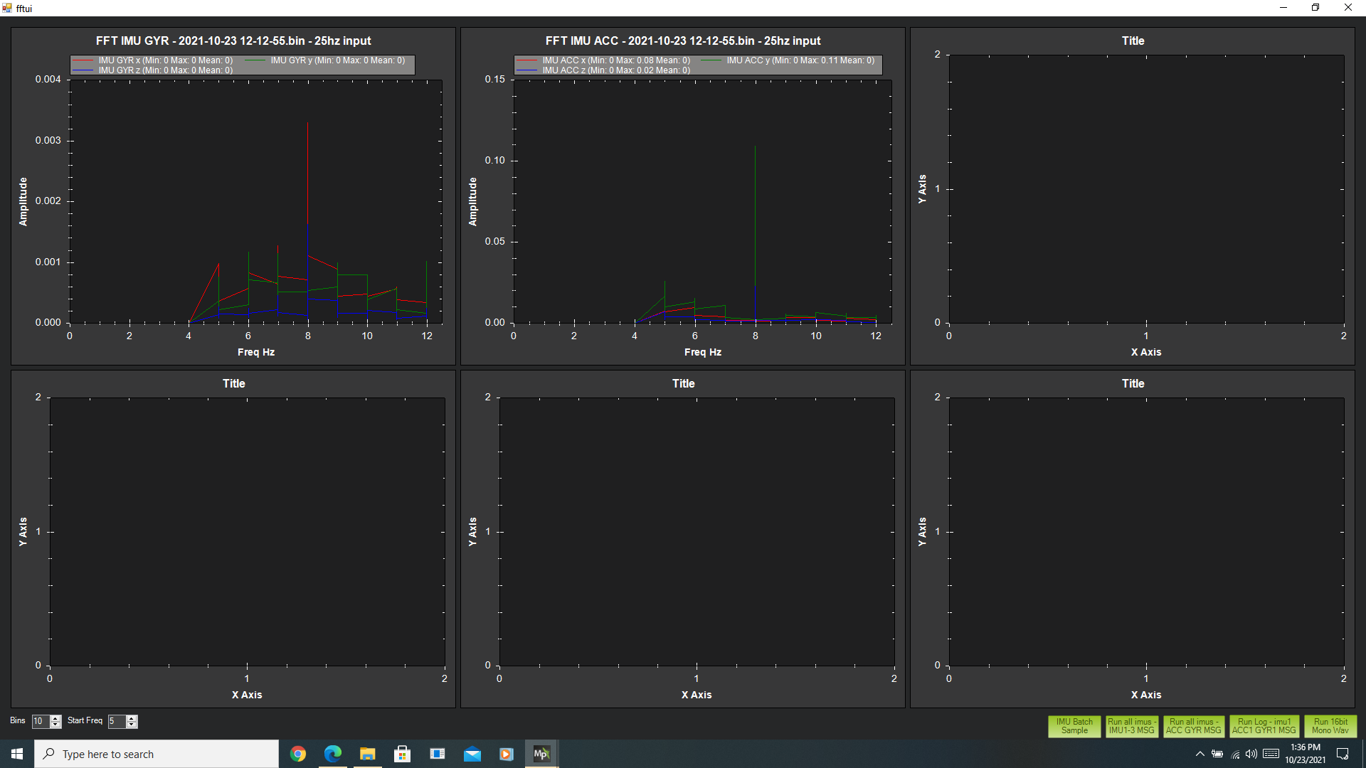
Unfortunately, the documentation isn’t up to date with the current FFT option from the CNTL-F menu in Mission Planner.
Only one of the graph options works “RUN ALL IMUS - IMU1-3 MSG” - and it doesn’t generate the same results as what I’ve depicted from the instructions on using FFT.
I saw someone else mention needing these two parameters:
INS_LOG_BAT_MASK,1
INS_LOG_BAT_OPT,2
As it happened, no IMU’s were set in the ins_log_bat_mask, and nothing was set for ins_log_bat_opt.
I set the mask to include all 3 IMU’s, and set the opt to 2. Then did another test flight.
The end result was the same graph - showing the same graph as before and still a sample rate of 25 hz. So somewhere in the pile of parameters it seems there’s something else that needs to be selected.
Hi Joe- Post your log or parameter file if you like, we can take a look.
INS_LOG_BAT_MASK,1 will log the 1st IMU which is all that is really required.
INS_LOG_BAT_OPT, 2 is post filter and what you would use to review the Dynamic Notch filter settings. If you set it to 0 it’s pre-filter and what you would use when you want to determine the proper filter settings. So:
_OPT to 0 and make a short AltHold Hover flight
Review the log and configure the filter
_OPT to 2 to see how well it’s working.
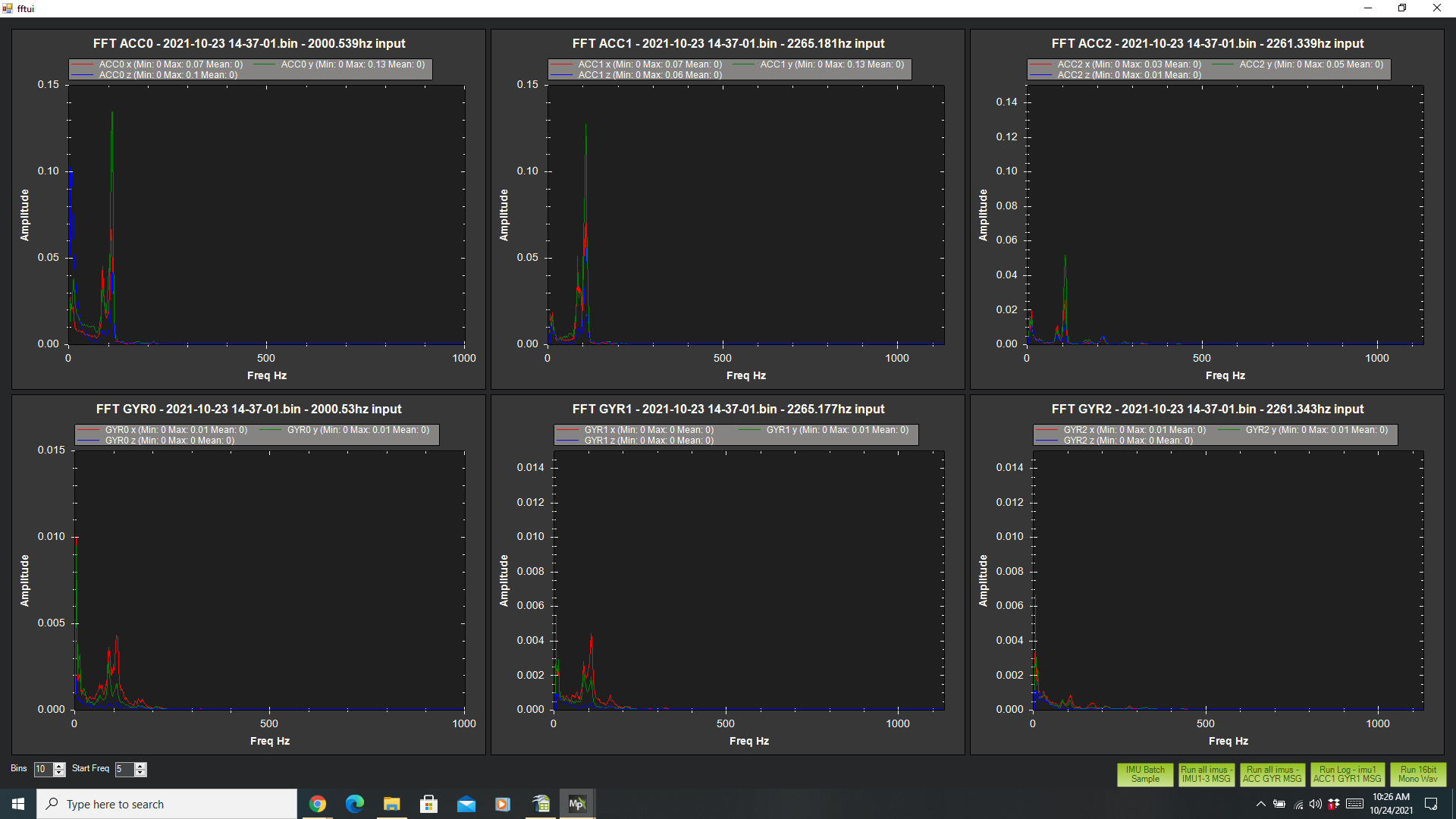
How on earth did you get that graph from my BIN file???
I get it about disabling the static notch filter - I should have thought of that.
I have both INS_ACCL_FILTER and INS_GYRO_FILTER set. (20 and 42 respectively)
When I reviewed my tuning parameters, I couldn’t figure out how INS_ACCL_FILTER got set to “20” - maybe it was in the default parameters when I loaded the firmware.
INS_GYRO_FILTER was set to 42 upon the recommendation of the ALT-A plug-in.
Do I set both of these to “0” - or only one - and if so - which one? (are there any others?)
Many thanks - and please tell me how you managed to get that graph!!
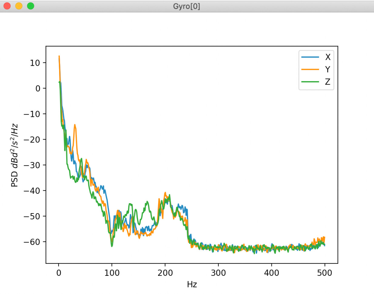
I’m following the ArduPilot documented procedure: Managing Gyro Noise with In-Flight FFT
There’s a step where it shows a graph to generate validate what’s been done.
To run that graph a user has to use a Python program in some sort of Python library/repository - plus, of course, have Python available on the user’s computer.