I have a maddening issue and hope someone can help. I built a large quad with the Pixhawk 4 and PM07 to power the ESCs. ESCs wires are soldered to their respective motor number on the PM. I have flown the quad several times and even tuned it. After I was confident the drone was ready for work I mounted the A6000 camera on it and have tried every parameter and port/servo I could think of. I also tried many suggestions from people with other Pixhawk controllers.
At this point the camera will trigger when I connect it to the servo pin or even when I turn the camera on while plugged in the the drone. I am using a shutter cable to servo connector. When I trigger the camera in mission planner or on the remote, an image icon appears in mission planner but the camera does not actually trigger. I have the FC connected to PM via IO out to IO in.
I read something about output groups but do not understand that. Maybe that is why I cant trigger the camera.
I used the shutter cable from a wired release button I had. Some generic brand. When I touch the ground focus and shutter pins together it triggers. Here is a parameter file. I have changed the setting so many times Im not sure what they were in this file. PixHawk_4_031621.param (18.4 KB)
I just have never heard or used the 101-106 so I had put it where it made since in my head. On the original PixHawk the motors were on the rail and anything else went next to that. So it had me a little confused
I have the IO out to IO in cable connecting the PH4 to the PM. If I connect the cable from IO in to FMU out I get motors working but no camera. Now with IO out to IO in and BRD set to 4 which FMU pins do I use for the camera?
Thank you for all the help. I was able to find and fix the issue. The cable I used was backward from the factory. Red was ground and Black was the shutter release.
For others that come across this post.
Below are the settings that worked for me. I will make a video on YouTube documenting the process for others that have similar problems. Video (when posted) can be found at GM6 Drone Mapping
Parameters as follows:
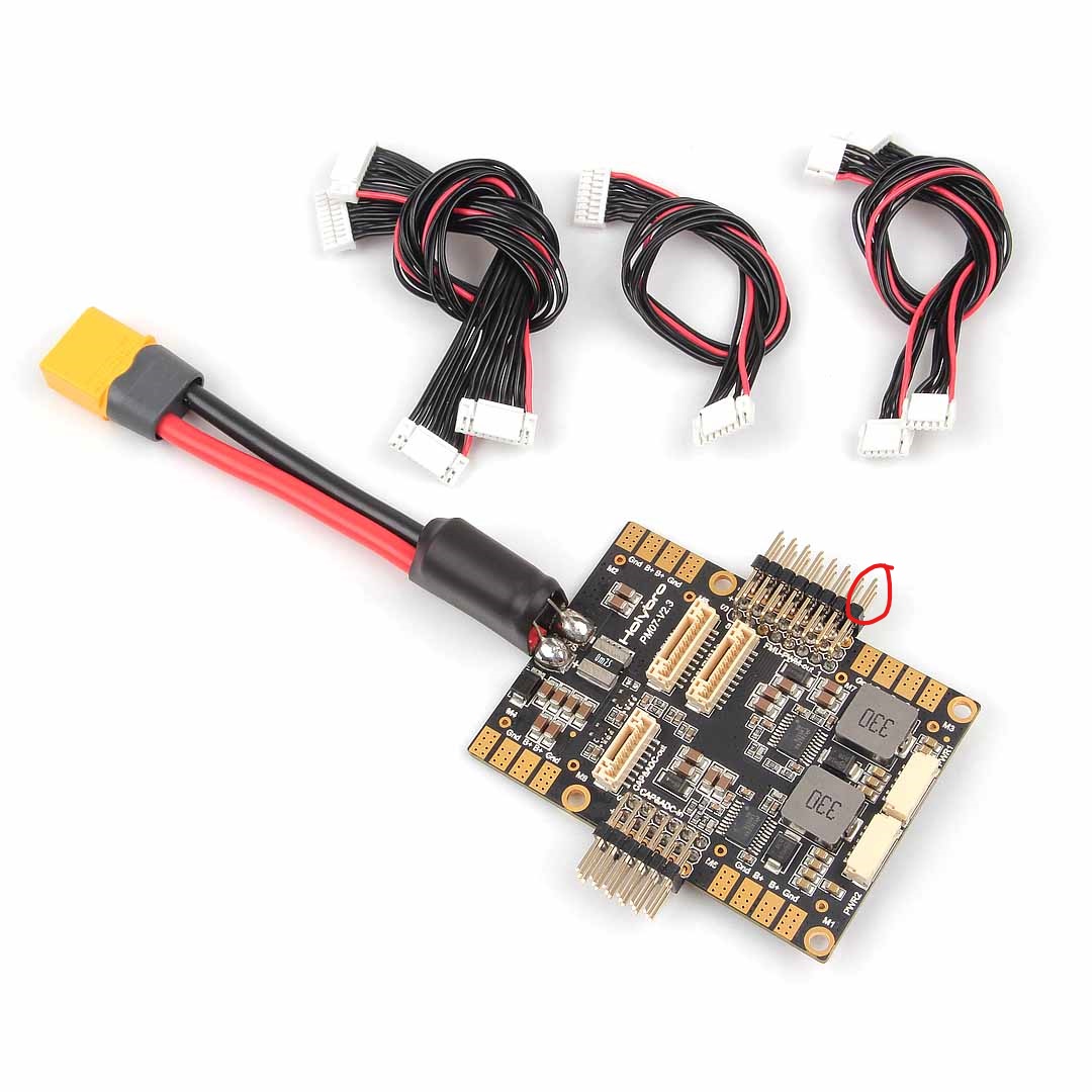
PixHawk 4 with Power Module 07
-BRD_PWM_COUNT = 0
-CAM_TYPE = 0
-CAM_RELAY_ON = 1
-CAM_TRIG_TYPE = 1
-CAM_DURATION = 1
-SERVO9_FUNCTION = 10
-RELAY_PIN = 50
-RELAY_DEFAULT = 0
Yes I am positive. I have conducted a couple of successful mapping missions since this setup. On the power board there are 8 servo pins on the rail. Supposedly they can be used as 8 IO or FMU I think is what I read. But then I thought IO was FMU so Im not sure but the pins can be used for dual purpose. All motors are wired directly to the board so none of the pins are used for signals.