Have updated my initial post above
My next challenge is to get the camera port to work on the CM4 carrier board. camera and code work perfectly on a standard Pi4 but for some reason the CM4 baseboard simply doesnt see the camera… the struggle continues.
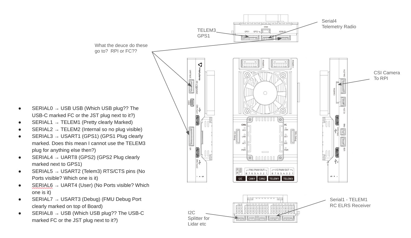
I have review the information and it looks like the Serial 6 is connected to UART4, and the port that goes to UART4 on the CM4 has the Silk Screen UART&I2C.. Sorry for the confusion.
Note that the TEL2 (Serial2) is connected internally between the FC & CM4 if you are using the Pixhawk CM4 baseboard. More information can be found here: Connections & Ports - Holybro Docs
Hello @VPHB Vince, quick question. If I wanted to control a servo with this CM4-PX6 board, through the CM4 module, I am guessing that I would have to send a mavlink message from the CM4 to the FC correct?
I have an external, regular RPi 4B that needs to communicate with the on board CM4 module, i.e., it will tell the CM4 to activate the servo at specific times (via wifi or Bluetooth), and since there are no CM4 GPIO pins, I will have to connect the servo directly to the baseboard GPIO, so when the external RPi tells the CM4 to activate the servo, the CM4 will then have to relay the message to the FC. This will have to be a mavlink message, correct?
Hey @tegwin, did you ever get the camera and code working… are you flying and using the camera with this cool PX6-CM4 board yet? If so, how’d it go?
I am currently starting my path down a similar route and I am making sure that everything I need my craft to do is possible. Like you, I need to use the camera port, along with both host ports to have another camera (one pointing down and the other forward) and a Coral edge TPU (USB accelerator). I want to run some detection and classification stuff on the two cameras (one CSI RPi cam and the other a USB cam), if possible, so I was wondering if you are working on something similar, which it sounds like you are.
Currently, I am trying to figure out how I am going to comunicate with the onboard CM4 from an external RPi 4B. The external one needs to tell the drone to activate a servo.
I really wish Holybro had a complete set of documentation for the base-board with ALL the pin outs!
I believe that the port labelled “A/D &IO” might be connected to the CM4 IO pins?!
Whilst I am having a grumble - it would have been so useful to have a JST-GH socket for CM4 power - relying on an external USB C connector is a bit clunky. Can’t complain too much - this device is much more integrated than any Cube product so far.
If you are wanting to connect an external Pi4 to the CM4 then the best method would be to connect them together via ethernet cable… We are using Bluerobotics botblox mini network switches.
The same with multiple cameras - if you can access the video over ethernet it makes life a lot easier.
Yes, we are doing something similar but I can’t go into that.
I do now have the pi-camera working via the CSI port. So far I have not been able to get the CM4 to reliably communicate with the FCU over internal serial. There’s probably some nuance that I am missing. Work continues on this. The only documentation I can find on this topic is aimed at Px4 - now it should be a similar connection for ardupilot but for some reason I don’t get a solid connection.
Managed a hover test with the FCU and so far the autopilot side of things seems to be working ok.
I can’t get the camera to be detected on the RPI CM4 board with the sudo raspi-config menu, nor with rpicam-hello. Have tried both the HQ Camera and Module 3 and definitely have my cables properly inserted but it just doesn’t see it. Would be hugely grateful to learn how you managed to get it working?
You’re an absolute hero. Disabling camera autodetect and adding the camera config made it work instantly. Almost all the guides online reference the interfaces menu but its clear that now those are obsolete for modern versions. Thanks once again!
Out of interest where would you connect Cam0 if there is only one CSI port on the baseboard? Not sure I quite understand the significance or opportunities for setting up Cam0?
But another camera can be connected via the CM4 host USB-C port, correct?
I’m planning on connecting two cameras in this way (i.e., one through CSI and one via USB), and also the Google Coral USB accelerator to use the two extra CM4 host ports.
I feel your pain. . . I have the Pixhawk CM (but don’t currently use the rpi). I used SERIAL5/UART2/TELEM3 for my RC receiver - underneath my I/O PWM servo1 and servo3 connectors.
Was confusing initially as TELEM2 is an internal connection to the compute module - looked all over for that one. . .
I wound up hooking things up like the image below. Got Mission Planner to recognize everything so far as well. I did send Holybro support an email to ask them for some clarifications as well. When and if I get a response Ill post it here.
The UART/I2C port on the side near the SPI port appears to be UART4, with the typical I2C pins interspersed, which is useful for (but not limited to) GPS/compass modules.
The SPI port is for SPI devices. They are somewhat uncommon as external peripherals.
The AD/IO port exposes a couple of ADCs for current monitoring or other analog sensors, along with mostly debug features on the other pins.
You can use any UART for any serial peripheral. The labels are merely suggestions. Sometimes they are very good suggestions because of the data /memory requirements associated with some peripherals.
Yelling at Holybro on this site probably won’t do anything useful. This isn’t their support site.
Moreover, what is it that you haven’t been able to do? The documentation looks pretty solid to me other than the unfortunate labeling of UART4. Your frustration seems more broadly directed at tackling the learning curve of using any autopilot vs the idiosyncrasies of this carrier.