Had a few requests to share more details on the HexArray WiFi array we have built to support a few projects.
Background
Before I start just remember that this was an experiment. I am not an RF geek. Rules of thumb were used and possibly harmed in the making of this device. I am a huge fan of using WiFi for telemetry and comms with robots. The tech has been around for some time; there are nice parts that are easy to source and affordable; the regulatory domain is understood; solid security is available; and keeping all data on an IP network makes sense to me. While the latest version was designed using mostly rules of thumb, the foundation was based off of an early prototype that was a Senior Design Project we sponsored a few years ago. As a result, there was some proper math and RF simulation used in an early version. I found it particularly fun to teach CS/EE students how to build a composite shell for the device. Details are here: http://projects-web.engr.colostate.edu/ece-sr-design/AY14/HexArray/index.html
Goal
Create a mobile WiFi array with hemispherical coverage that can support up to twelve airborne robots out to 1 mile line of site; all using off the shelf electronics.
- Use 5.8GHz to stay away from 2.4 RC
- Use 802.11a to minimize hardware (antenna and WiFi dongle) requirements and help with range
- Support unlicensed use in most countries
- Support h.264 720P@10FPS video streaming out to 1/2 mile
- Support 640 x 480@10fps video and full telemetry out to 1 mile
- Client devices should not need special settings to roam on array
- Allow for support of small mapping/video relay server and/or RTK device
- Allow network to scale with multiple arrays
Although testing of the early version showed we could meet or exceed the performance goals, it was also running 802.11n at 2.4GHz. The 5.8Ghz version has been used with success for copters at less than 1/2 mile, but it has not had any formal testing completed.
Concept
This design is essentially a three sector array that is geometrically optimized (that’s a strong word, but that was the goal) to provide a long range hemispherical Access Point for stuff that flies. Your typical sector array on a tower is optimized for clients roaming around on the ground with a very narrow horizontal beam width, and is usually huge. We needed something smaller with a bigger field of view. Each sector in this design is two radios and antennas that cover 60 deg each horizontally and 180 deg vertically: 120 x 180 total. The idea being that if you were over the device you should be fairly close, so our hemisphere is not really a sphere. Some smart readers may also notice were are using antennas that have 120deg+ horizontal beam width, but use them for a 60deg coverage. True, but we wanted longer range so only use the 60 deg center portion of the horizontal antenna beam, and use two for longer range. We also have highly mobile clients that sometimes fly over water and in/around obstacles so circular polarization was chosen to minimize multi-path and signal loss while in turns. Thanks to the cool FPV antennas out there that was one of the easier parts. We thought about using right and left hand polarization with MIMO WiFi and decided it would be awesome for short range copter video rigs but not as mature, versatile or simple as 802.11a that only needs a single stream. Simple being the key here we opted for 802.11a and right hand circular polarization. I’ll also note here that you do not need to run all three sectors. I have built a smaller version with just one sector for basic use.
Build
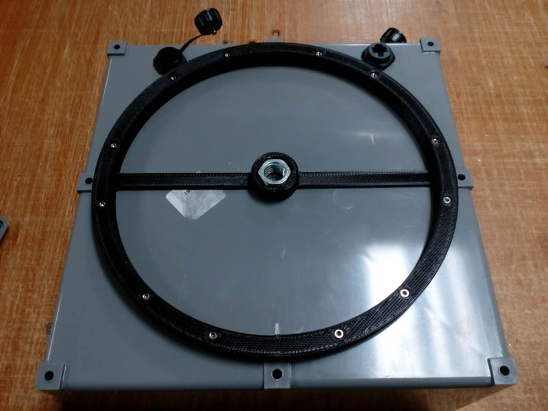
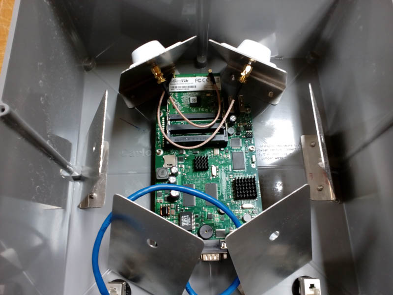
The latest version looks like this: Mikrotik RouterBoard with three PCIe WiFi cards; each card running two radios with RHCP FPV antennas; an Emlid Reach connected via USB with a GNSS antenna and ground plane; a few 3D printed parts to help with mounting; all stuffed in/on a 12in x 12in PVC junction box
Base BOM
These are the big parts. Stuff like cables is left to reader:
- (1) RouterBoard: RB433UL https://mikrotik.com/product/RB433UL
- (3) Interface: R52NM https://mikrotik.com/product/R52NM
- (6) Antennas: X-AIR 5.8 https://www.truerc.ca/shop/antennas/5-8ghz/x-air-5-8
- (1) Enclosure: 12 x 12 PVC junction box or similar
- (1) Power Supply: Passive POE or DC barrel jack
Roaming
Perhaps one of the biggest challenges in a device like this is how to support clients roaming from one sector to another without dropping a bunch of packets. Seamless roaming and fast hand-off are a couple terms that come to mind when you start searching around for solutions. There are a few ways to support this type of roaming and most are proprietary. The first version we built used Ubiquiti Unifi equipment. If you setup Unifi gear on the same SSID you can shut down the central mesh controller and the units will handle roaming in the background. Works really well from our experiments. Problem was it took 6 separate Ubiquiti radios, which needed a bunch of POE power coming from a switch. Just made things too big and complex. Technically you could mount all this stuff on a small pole with a tripod and call it good. We were looking for something that was more mobile and could be mounted on a car/boat roof. So we settled on the MiktroTik RouterBoard(RB) with 3 high power PCIe cards( called interfaces in this context). To get our clients to roam using this setup we use the same SSID on all interfaces (all on different channels to minimize interference) with an Access Control List (ACL) on the RouterBoard(RB). Mikrotiks’s RouterOS lets you setup an ACL based on client RSSI. So to keep your client from sticking to a sector with low signal we use the ACL to forcibly kick the client at around -80db. The client than (theoretically) reconnects to the AP sector with highest signal. In our testing we did see some packet loss in video streams when switching, but it has worked well enough for our purposes so far. An area that needs much more testing to make any concrete claims. Miktorik also has more robust features to handle roaming called CAPSMan but that is not something we have tried yet, it’s fairly complex, and this post is already getting really long. Using the ACL RSSI trick is simple and it works for basic use.
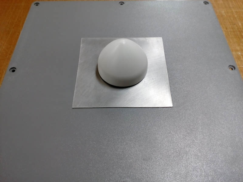
RTK Base
This version also ended up with an RTK Base using an Emlid Reach. Since there is potential for all this WiFi gear to cause out of band interference with RTK GNSS it needs a bunch more testing as well. One idea is to put the entire RTK setup up on a short mast above the PVC junction box. Since we are using PVC there are plenty of parts at a well stocked hardware store to make that happen. But basic testing shows it works well enough to achieve a fix in clear sky conditions wile the array is running. The Reach is connected to the RouterBoard via USB and a USB to serial adapter. The RouterBoard allows you to setup a USB port as a telnet server, so the Reach is passing corrections via TCP to that port. You can then use Mission Planner to connect for RTK Inject Sadly this locks the port, only one connection at a time. A better solution is to likely add a small embedded Linux server running SNIP so you can handle a few more connections to RTK Base. This same server could be used for things like maps and video relay.
Note About Client WiFi
All of the above assumes you have a robot with WiFi capability. I think most of us are using companion computers to run the WiFi, and connect to ArduPilot via serial. I am becoming a fan of the MinnowBoard with SilverJaw lure since it allows me to use a full size PCIe WiFi card. Not the cheapest option or really needed if you are just looking to do basic work. Just don’t expect a bunch of range from built in WiFi on most devices.
It can be hard to find good USB WiFi devices for the client/robot side. I have used this one with RPi and other small embedded Linux machines with some success:
You will need to compile drivers and I suggest putting it in a 3D printed case with a heatsink of some sort. Many of these “high gain/power” wifi dongles will power clamp if you run them hard for prolonged periods.
I have also heard good things about some of the Alfa’s dongles. The WifiBroadcast community is a good resource for WiFi dongles that work with minimum fuss and are also hackable if you want to go there.