Help understanding UART DMA requirements?

When deciding which UARTs to use for which peripherals (eg RC link, telemetry modem, GPS, etc), how does DMA enter the equation? And which peripherals require or perform better with DMA?

Some of the boards I’m working with (MatekF405, Omnibus F4, Flywoo F745) only have DMA on a single UART, or only have DMA on TX. What are the implications of this?

Do I need to put the RC Link (usually SBUS) on a DMA UART? Will MavLink telemetry work better (eg faster parameter download) when connected to a DMA UART? Is DMA TX sufficient, or do I need a full TX/RX DMA UART?

And finally, can DMA assignments be modified in hwdef? What considerations have to be made if so? And how does it affect motor outputs (assuming I’m using DSHOT)?

Generally the gating factor here is RX baudrate - anything over about 200kbaud will be too noisy to be read accurately by polling. DMA offloads the reading directly to the MCU and allows the data to be read very, very evenly regardless of what other things the CPU is processing. So rule of thumb - anything that requires a baudrate > 200kbaud requires DMA. The exception to this is that on H7 there is a UART FIFO buffer that allows reads to be processed evenly enough without using DMA (although on H7 the DMA options are more flexible anyway so its not such a benefit). DMA also allows UARTs to be read reliably in the presence of high load - for instance on F4 CPUs which are already pretty loaded. So there are no hard and fast rules but:

  • CRSF definitely requires DMA - 416kbaud
  • GPS likely to require DMA - 234kbaud (especially when using high bandwidth things like RTK)
  • Companion computer - likely to require DMA
  • High rate sensor data of any kind

Everything else not so much, but anything that is flight critical is likely to benefit - so for instance you don’t have to use DMA for SBUS but you might benefit from it

Things that really don’t need DMA are slow things, so for example:

  • SmartAudio
  • RunCam

mavlink is unlikely to benefit. RX is the main one, TX can also benefit but we share DMA channels for TX so there can be contention between devices

You can change DMA assignments in hwdef but its a dark art - the script will simply not assign DMA channels if it cannot and you need to look in hwdef.h to see what got allocated and what not. You can change this behavior a bit through the use of DMA_PRIORITY and DMA_NOSHARE

3 Likes

Thank you! Is it possible to tell from the datasheet which UARTs can be assigned DMA? I checked the STM32F405 datasheet and don’t see any reference to DMA for the UARTs.

Where do I find hwdef.h? I’m familiar with hwdef.dat, but it’s not clear how DMA is assigned.

All UARTS can be assigned DMA, the constraint is that there are only so many DMA channels and not all of them can be shared. When you build - builds//hwdef.h is a generated file

Thanks Andy! I found some interesting discussion in the CRSF passthrough telemetry thread as well.

If I’m not using RTK, is there any benefit to running a GPS at 234kbaud vs 115k?

F405 boards are going to be severely limited on DMA, right? I think they only have one full DMA UART.
How about F745 and F765 boards?

Its not that F4 and F7 have fewer DMA channels, its that there is limited flexibility in what channels can be assigned to which functions. How this works out in practice is really down to the pin assignments that the vendor has decided on. H7 is much better because there are no restrictions on assignment.

1 Like

I’m still not understanding some key part of DMA assignments then, and haven’t been able to fill in the missing piece yet from the datasheets.

Is the limitation on which DMA channels can be assigned to which functions a timer limitation? That is, only certain timers are able to generate DMA requests, so you are limited by which timers and channels you can assign to a resource?

Not just timers, look at DMA_Map in libraries/AP_HAL_ChibiOS/hwdef/scripts/STM32F405xx.py to see the allowable channel assignments for F405 - this table is generated from the datasheet

1 Like

I finally found the appropriate table in the STM32 reference manual for DMA Mapping, and see how the allowable channel assignments are generated in STM32F405xx.py. However, I’m still not seeing where the conflict is between DMA assignments.

Perhaps explaining this issue would help clarify things for me: AP_HAL_ChibiOS: make sure all MatekF405 bi-dir outputs get a DMA channel · ArduPilot/ardupilot@d36b4bf · GitHub

# Can only do bdshot on M1-4, so give up DMA channels on M5/M6 to get full DMA on USART3 and UART4
PA15 TIM2_CH1 TIM2 PWM(5) GPIO(54) NODMA
PA8  TIM1_CH1 TIM1 PWM(6) GPIO(55) NODMA

So the DMA assignments are removed for TIM2_CH1 and TIM1_CH1, which allows DMA to be assigned to USART3 and UART4. From the DMA map, TIM2_CH1 uses DMA1, Stream 5 Ch 3, and TIM1_CH1 uses DMA2, Stream 6 Ch 0, Stream 1 Channel 6, or Stream 3 Channel 6. However, none of these share a stream with USART3 or UART4. I’m not following how giving up DMA on those timers allows full DMA on those UARTs.

Edit: I see the Motor 1 output on C6 was moved from TIM3_CH1 to TIM8_CH1, which frees up DMA1 Stream 4. This stream can also be used for UART4_TX and USART3_TX. Can a DMA stream be shared between UARTs? Or would UART4_TX use Stream 4, and USART3_TX use Stream 3?

Is there an easy way to see which resources have which DMA assignments for the precompiled targets?

It’s a little dance and its made harder to understand by our script which allocates the DMA channels - so you might have a chain of three or four peripherals where if you change one of the DMA allocations has a ripple effect in the chain allowing something else.

There’s no easy way to see what happened except by looking at the generated hwdef.h. I nice enhancement would be to get configure to spit out a human readable summary of DMA allocations.

DMA channels can be shared on UART TX but not not UART RX

1 Like

Ok, knowing that DMA can be shared for UART TX but not RX is an important piece I was missing. Can PWM timers be shared between streams? What other resources on a F405 FC require DMA (eg ADC, I2C, SPI), and which require their own streams?

In the PR linked above, it is noted that you can only do bdshot on M1-4. Why can’t M5 and/or M6 run bdshot? What is needed for bdshot besides a timer and DMA stream?

My goal is to compile Plane firmware for the Matek F405 that supports a single bdshot channel for the ESC, while keeping the remaining outputs on a separate timer (or timers) for servo use.

I compiled a new version based off MatekF405-bdshot, with the following hwdef.dat:

include ../MatekF405/hwdef.dat

undef PC6 PA8 PA15 PC12

#Move PWM1 to TIM8 to free up DMA1 Stream2 for UART4_RX
PC6  TIM8_CH1 TIM8 PWM(1) GPIO(50) 
#Remove DMA from TIM2 to free up DMA1 Stream1 for USART3_RX
PA15  TIM2_CH1 TIM2 PWM(5) GPIO(54) NODMA
#Make PWM6 BDShot Output
PA8  TIM1_CH1 TIM1 PWM(6) GPIO(55) BIDIR
#Remove DMA from UART5_TX to prevent conflict on DMA1 Stream7
PC12 UART5_TX UART5 NODMA

Compiling gives me the following hwdef.h:

***snip***
// auto-generated DMA mapping from dma_resolver.py

// Note: The following peripherals can't be resolved for DMA: ['UART5_RX']

#define STM32_ADC_ADC1_DMA_STREAM      STM32_DMA_STREAM_ID(2, 4)
#define STM32_ADC_ADC1_DMA_CHAN        0
#define STM32_I2C_I2C1_RX_DMA_STREAM   STM32_DMA_STREAM_ID(1, 5)
#define STM32_I2C_I2C1_RX_DMA_CHAN     1
#define STM32_I2C_I2C1_TX_DMA_STREAM   STM32_DMA_STREAM_ID(1, 6)
#define STM32_I2C_I2C1_TX_DMA_CHAN     1
#define STM32_SPI_SPI1_RX_DMA_STREAM   STM32_DMA_STREAM_ID(2, 0)
#define STM32_SPI_SPI1_RX_DMA_CHAN     3
#define STM32_SPI_SPI1_TX_DMA_STREAM   STM32_DMA_STREAM_ID(2, 3)
#define STM32_SPI_SPI1_TX_DMA_CHAN     3
#define STM32_SPI_SPI2_RX_DMA_STREAM   STM32_DMA_STREAM_ID(1, 3)
#define STM32_SPI_SPI2_RX_DMA_CHAN     0
#define STM32_SPI_SPI2_TX_DMA_STREAM   STM32_DMA_STREAM_ID(1, 4) // shared SPI2_TX,USART3_TX,UART4_TX
#define STM32_SPI_SPI2_TX_DMA_CHAN     0
#define STM32_SPI_SPI3_RX_DMA_STREAM   STM32_DMA_STREAM_ID(1, 0)
#define STM32_SPI_SPI3_RX_DMA_CHAN     0
#define STM32_SPI_SPI3_TX_DMA_STREAM   STM32_DMA_STREAM_ID(1, 7)
#define STM32_SPI_SPI3_TX_DMA_CHAN     0
#define STM32_TIM_TIM1_CH1_DMA_STREAM  STM32_DMA_STREAM_ID(2, 6)
#define STM32_TIM_TIM1_CH1_DMA_CHAN    0
#define STM32_TIM_TIM1_UP_DMA_STREAM   STM32_DMA_STREAM_ID(2, 5)
#define STM32_TIM_TIM1_UP_DMA_CHAN     6
#define STM32_TIM_TIM8_UP_DMA_STREAM   STM32_DMA_STREAM_ID(2, 1)
#define STM32_TIM_TIM8_UP_DMA_CHAN     7
#define STM32_UART_UART4_RX_DMA_STREAM STM32_DMA_STREAM_ID(1, 2)
#define STM32_UART_UART4_RX_DMA_CHAN   4
#define STM32_UART_UART4_TX_DMA_STREAM STM32_DMA_STREAM_ID(1, 4) // shared SPI2_TX,USART3_TX,UART4_TX
#define STM32_UART_UART4_TX_DMA_CHAN   4
#define STM32_UART_USART1_RX_DMA_STREAM STM32_DMA_STREAM_ID(2, 2)
#define STM32_UART_USART1_RX_DMA_CHAN  4
#define STM32_UART_USART1_TX_DMA_STREAM STM32_DMA_STREAM_ID(2, 7)
#define STM32_UART_USART1_TX_DMA_CHAN  4
#define STM32_UART_USART3_RX_DMA_STREAM STM32_DMA_STREAM_ID(1, 1)
#define STM32_UART_USART3_RX_DMA_CHAN  4
#define STM32_UART_USART3_TX_DMA_STREAM STM32_DMA_STREAM_ID(1, 4) // shared SPI2_TX,USART3_TX,UART4_TX
#define STM32_UART_USART3_TX_DMA_CHAN  7

// Mask of DMA streams which are shared
#define SHARED_DMA_MASK ((1U<<STM32_DMA_STREAM_ID(1,4)))


// generated UART DMA configuration lines
#define STM32_USART1_RX_DMA_CONFIG true, STM32_UART_USART1_RX_DMA_STREAM, STM32_UART_USART1_RX_DMA_CHAN
#define STM32_USART1_TX_DMA_CONFIG true, STM32_UART_USART1_TX_DMA_STREAM, STM32_UART_USART1_TX_DMA_CHAN
#define STM32_USART2_RX_DMA_CONFIG false, 0, 0
#define STM32_USART2_TX_DMA_CONFIG false, 0, 0
#define STM32_USART3_RX_DMA_CONFIG true, STM32_UART_USART3_RX_DMA_STREAM, STM32_UART_USART3_RX_DMA_CHAN
#define STM32_USART3_TX_DMA_CONFIG true, STM32_UART_USART3_TX_DMA_STREAM, STM32_UART_USART3_TX_DMA_CHAN
#define STM32_UART4_RX_DMA_CONFIG true, STM32_UART_UART4_RX_DMA_STREAM, STM32_UART_UART4_RX_DMA_CHAN
#define STM32_UART4_TX_DMA_CONFIG true, STM32_UART_UART4_TX_DMA_STREAM, STM32_UART_UART4_TX_DMA_CHAN
#define STM32_UART5_RX_DMA_CONFIG false, 0, 0
#define STM32_UART5_TX_DMA_CONFIG false, 0, 0
// generated SPI DMA configuration lines
#define STM32_SPI_SPI1_DMA_STREAMS STM32_SPI_SPI1_TX_DMA_STREAM, STM32_SPI_SPI1_RX_DMA_STREAM
#define STM32_SPI_SPI2_DMA_STREAMS STM32_SPI_SPI2_TX_DMA_STREAM, STM32_SPI_SPI2_RX_DMA_STREAM
#define STM32_SPI_SPI3_DMA_STREAMS STM32_SPI_SPI3_TX_DMA_STREAM, STM32_SPI_SPI3_RX_DMA_STREAM
#define HAL_PWM_COUNT 6
// RC input config
#define HAL_USE_EICU TRUE
#define STM32_EICU_USE_TIM9 TRUE
#define RCININT_EICU_TIMER EICUD9
#define RCININT_EICU_CHANNEL EICU_CHANNEL_2


// No Alarm output pin defined
#undef HAL_PWM_ALARM

// PWM timer config
#define HAL_WITH_BIDIR_DSHOT
#define STM32_PWM_USE_TIM8 TRUE
#define STM32_TIM8_SUPPRESS_ISR
#define STM32_PWM_USE_TIM1 TRUE
#define STM32_TIM1_SUPPRESS_ISR
#define STM32_PWM_USE_TIM2 TRUE
#define STM32_TIM2_SUPPRESS_ISR

// PWM output config
#if defined(STM32_TIM_TIM8_UP_DMA_STREAM) && defined(STM32_TIM_TIM8_UP_DMA_CHAN)
# define HAL_PWM8_DMA_CONFIG true, STM32_TIM_TIM8_UP_DMA_STREAM, STM32_TIM_TIM8_UP_DMA_CHAN
#else
# define HAL_PWM8_DMA_CONFIG false, 0, 0
#endif

#if defined(STM32_TIM_TIM8_CH1_DMA_STREAM) && defined(STM32_TIM_TIM8_CH1_DMA_CHAN)
# define HAL_IC8_CH1_DMA_CONFIG true, STM32_TIM_TIM8_CH1_DMA_STREAM, STM32_TIM_TIM8_CH1_DMA_CHAN
#else
# define HAL_IC8_CH1_DMA_CONFIG false, 0, 0
#endif
#if defined(STM32_TIM_TIM8_CH2_DMA_STREAM) && defined(STM32_TIM_TIM8_CH2_DMA_CHAN)
# define HAL_IC8_CH2_DMA_CONFIG true, STM32_TIM_TIM8_CH2_DMA_STREAM, STM32_TIM_TIM8_CH2_DMA_CHAN
#else
# define HAL_IC8_CH2_DMA_CONFIG false, 0, 0
#endif
#if defined(STM32_TIM_TIM8_CH3_DMA_STREAM) && defined(STM32_TIM_TIM8_CH3_DMA_CHAN)
# define HAL_IC8_CH3_DMA_CONFIG true, STM32_TIM_TIM8_CH3_DMA_STREAM, STM32_TIM_TIM8_CH3_DMA_CHAN
#else
# define HAL_IC8_CH3_DMA_CONFIG false, 0, 0
#endif
#if defined(STM32_TIM_TIM8_CH4_DMA_STREAM) && defined(STM32_TIM_TIM8_CH4_DMA_CHAN)
# define HAL_IC8_CH4_DMA_CONFIG true, STM32_TIM_TIM8_CH4_DMA_STREAM, STM32_TIM_TIM8_CH4_DMA_CHAN
#else
# define HAL_IC8_CH4_DMA_CONFIG false, 0, 0
#endif
***/snip***

So 3 PWM groups (1-4, 5, 6) with BDShot on 6, and full DMA on USART1 (Serial 3), USART3 (Serial 1), and UART4 (Serial 2). I think the SPI, I2C, and ADC DMA assignments are still OK, but I still need to test.

Does anyone see any problems with the above?

Planning on having servos on 1-4, maybe WS2812 LED output on 5 for nav lights, and BDShot ESC on 6. I don’t need DMA for servos or LED PWM outputs, right?

Edit: Maybe I do need DMA for LEDs…

You definitely need DMA for LEDs

1 Like

Ok, I think I have this figured out. A better solution involves editing the MatekF405 hwdef.dat to include S7, but this involves using timer 4.

What are the restrictions on changing the system timer? Can I change this to Timer 14 without causing any issues?
define STM32_ST_USE_TIMER 4

Is there a reason the F405 uses a 16 bit timer by default? What effect on performance would using a 32 bit timer have?

ChibiOS will complain if its not allowed - so you can try it. Some boards using 16bit for system timer ok (e.g. Matek H743)

Thanks for your help!

I think I can finally wrap my head around this enough to edit hwdef.dat and get the desired changes in DMA mapping. Can someone take a look and verify this all makes sense?

Here is the edited hwdef.dat I made for my MatekF405 board to: add bi-directional DSHOT to M6, add PWM S7, enable full DMA on USART1, USART3, and UART5.

# Need to free TIM4 for S7 (Pin B8, PWM 7, GPIO 56). Move system timer to TIM14, which should be equivalent.
- define STM32_ST_USE_TIMER 4
+ define STM32_ST_USE_TIMER 14

# Don't assign DMA to TIM3 to free up DMA1 Stream 2 for SPI3_RX
- PC6  TIM3_CH1 TIM3 PWM(1) GPIO(50)
+ PC6  TIM3_CH1 TIM3 PWM(1) GPIO(50) NODMA

# Don't assign DMA to TIM2 to free up DMA1 Stream 1 for USART3_RX
- PA15 TIM2_CH1 TIM2 PWM(5) GPIO(54)
+ PA15 TIM2_CH1 TIM2 PWM(5) GPIO(54) NODMA

# Enable bidirectional DShot on M6
- PA8  TIM1_CH1 TIM1 PWM(6) GPIO(55)
+ PA8  TIM1_CH1 TIM1 PWM(6) GPIO(55) BIDIR

# Enable PWM output on S7 (Pin B8)
+ PB8  TIM4_CH3 TIM4 PWM(7) GPIO(56)

# Make sure USART3_RX and UART5_RX are assigned DMA streams to enable full DMA
+ DMA_PRIORITY USART3_RX UART5_RX 

And the resulting hwdef.h: hwdef.h (62.7 KB)

Relevant hwdef.h code snippet:

// GPIO config
#define HAL_GPIO_LINE_GPIO0 PAL_LINE(GPIOB,9U)
#define HAL_GPIO_LINE_GPIO1 PAL_LINE(GPIOA,14U)
#define HAL_GPIO_LINE_GPIO50 PAL_LINE(GPIOC,6U)
#define HAL_GPIO_LINE_GPIO51 PAL_LINE(GPIOC,7U)
#define HAL_GPIO_LINE_GPIO52 PAL_LINE(GPIOC,8U)
#define HAL_GPIO_LINE_GPIO53 PAL_LINE(GPIOC,9U)
#define HAL_GPIO_LINE_GPIO54 PAL_LINE(GPIOA,15U)
#define HAL_GPIO_LINE_GPIO55 PAL_LINE(GPIOA,8U)
#define HAL_GPIO_LINE_GPIO56 PAL_LINE(GPIOB,8U)
#define HAL_GPIO_LINE_GPIO80 PAL_LINE(GPIOC,13U)
#define HAL_GPIO_PINS { \
{   0, true,  0, PAL_LINE(GPIOB,9U)}, /* PB9 LED_BLUE OUTPUT */ \
{   1, true,  0, PAL_LINE(GPIOA,14U)}, /* PA14 LED_GREEN OUTPUT */ \
{  50, true,  1, PAL_LINE(GPIOC,6U)}, /* PC6 TIM3_CH1 TIM3 AF2 PWM1 */ \
{  51, true,  2, PAL_LINE(GPIOC,7U)}, /* PC7 TIM8_CH2 TIM8 AF3 PWM2 */ \
{  52, true,  3, PAL_LINE(GPIOC,8U)}, /* PC8 TIM8_CH3 TIM8 AF3 PWM3 */ \
{  53, true,  4, PAL_LINE(GPIOC,9U)}, /* PC9 TIM8_CH4 TIM8 AF3 PWM4 */ \
{  54, true,  5, PAL_LINE(GPIOA,15U)}, /* PA15 TIM2_CH1 TIM2 AF1 PWM5 */ \
{  55, true,  6, PAL_LINE(GPIOA,8U)}, /* PA8 TIM1_CH1 TIM1 AF1 PWM6 */ \
{  56, true,  7, PAL_LINE(GPIOB,8U)}, /* PB8 TIM4_CH3 TIM4 AF2 PWM7 */ \
{  80, true,  0, PAL_LINE(GPIOC,13U)}, /* PC13 BUZZER OUTPUT */ \
}

// full pin define list
#define HAL_GPIO_PIN_BATT_CURRENT_SENS    PAL_LINE(GPIOC,4U)
#define HAL_GPIO_PIN_BATT_VOLTAGE_SENS    PAL_LINE(GPIOC,5U)
#define HAL_GPIO_PIN_BUZZER               PAL_LINE(GPIOC,13U)
#define HAL_GPIO_PIN_I2C1_SCL             PAL_LINE(GPIOB,6U)
#define HAL_GPIO_PIN_I2C1_SDA             PAL_LINE(GPIOB,7U)
#define HAL_GPIO_PIN_I2C1_SCL             PAL_LINE(GPIOB,6U)
#define HAL_GPIO_PIN_LED_BLUE             PAL_LINE(GPIOB,9U)
#define HAL_GPIO_PIN_LED_GREEN            PAL_LINE(GPIOA,14U)
#define HAL_GPIO_PIN_M25P16_CS            PAL_LINE(GPIOC,0U)
#define HAL_GPIO_PIN_MAX7456_CS           PAL_LINE(GPIOB,10U)
#define HAL_GPIO_PIN_MPU6000_CS           PAL_LINE(GPIOC,2U)
#define HAL_GPIO_PIN_OTG_FS_DM            PAL_LINE(GPIOA,11U)
#define HAL_GPIO_PIN_OTG_FS_DP            PAL_LINE(GPIOA,12U)
#define HAL_GPIO_PIN_RSSI_ADC_PIN         PAL_LINE(GPIOB,1U)
#define HAL_GPIO_PIN_SDCARD_CS            PAL_LINE(GPIOC,1U)
#define HAL_GPIO_PIN_SPI1_MISO            PAL_LINE(GPIOA,6U)
#define HAL_GPIO_PIN_SPI1_MOSI            PAL_LINE(GPIOA,7U)
#define HAL_GPIO_PIN_SPI1_SCK             PAL_LINE(GPIOA,5U)
#define HAL_GPIO_PIN_SPI2_MISO            PAL_LINE(GPIOB,14U)
#define HAL_GPIO_PIN_SPI2_MOSI            PAL_LINE(GPIOB,15U)
#define HAL_GPIO_PIN_SPI2_SCK             PAL_LINE(GPIOB,13U)
#define HAL_GPIO_PIN_SPI3_MISO            PAL_LINE(GPIOB,4U)
#define HAL_GPIO_PIN_SPI3_MOSI            PAL_LINE(GPIOB,5U)
#define HAL_GPIO_PIN_SPI3_SCK             PAL_LINE(GPIOB,3U)
#define HAL_GPIO_PIN_TIM1_CH1             PAL_LINE(GPIOA,8U)
#define HAL_GPIO_PIN_TIM2_CH1             PAL_LINE(GPIOA,15U)
#define HAL_GPIO_PIN_TIM3_CH1             PAL_LINE(GPIOC,6U)
#define HAL_GPIO_PIN_TIM4_CH3             PAL_LINE(GPIOB,8U)
#define HAL_GPIO_PIN_TIM8_CH2             PAL_LINE(GPIOC,7U)
#define HAL_GPIO_PIN_TIM8_CH3             PAL_LINE(GPIOC,8U)
#define HAL_GPIO_PIN_TIM8_CH4             PAL_LINE(GPIOC,9U)
#define HAL_GPIO_PIN_TIM9_CH2             PAL_LINE(GPIOA,3U)
#define HAL_GPIO_PIN_UART4_RX             PAL_LINE(GPIOA,1U)
#define HAL_GPIO_PIN_UART4_TX             PAL_LINE(GPIOA,0U)
#define HAL_GPIO_PIN_UART5_RX             PAL_LINE(GPIOD,2U)
#define HAL_GPIO_PIN_UART5_TX             PAL_LINE(GPIOC,12U)
#define HAL_GPIO_PIN_USART1_RX            PAL_LINE(GPIOA,10U)
#define HAL_GPIO_PIN_USART1_TX            PAL_LINE(GPIOA,9U)
#define HAL_GPIO_PIN_USART2_TX            PAL_LINE(GPIOA,2U)
#define HAL_GPIO_PIN_USART3_RX            PAL_LINE(GPIOC,11U)
#define HAL_GPIO_PIN_USART3_TX            PAL_LINE(GPIOC,10U)
#define HAL_GPIO_PIN_VBUS                 PAL_LINE(GPIOB,12U)

#define HAL_INS_PROBE1  ADD_BACKEND(AP_InertialSensor_Invensense::probe(*this,hal.spi->get_device("mpu6000"),ROTATION_YAW_180))
#define INS_MAX_INSTANCES 1
#define HAL_INS_PROBE_LIST HAL_INS_PROBE1

#define HAL_BARO_PROBE1  ADD_BACKEND(AP_Baro_BMP280::probe(*this,GET_I2C_DEVICE(0,0x76)))
#define HAL_BARO_PROBE_LIST HAL_BARO_PROBE1

// peripherals enabled
#define STM32_I2C_USE_I2C1                  TRUE
#define STM32_USB_USE_OTG1                  TRUE
#define STM32_SPI_USE_SPI1                  TRUE
#define STM32_SPI_USE_SPI2                  TRUE
#define STM32_SPI_USE_SPI3                  TRUE
#ifndef STM32_SERIAL_USE_UART4 
#define STM32_SERIAL_USE_UART4  TRUE
#endif
#ifndef STM32_SERIAL_USE_UART5 
#define STM32_SERIAL_USE_UART5  TRUE
#endif
#ifndef STM32_SERIAL_USE_USART1
#define STM32_SERIAL_USE_USART1 TRUE
#endif
#ifndef STM32_SERIAL_USE_USART2
#define STM32_SERIAL_USE_USART2 TRUE
#endif
#ifndef STM32_SERIAL_USE_USART2
#define STM32_SERIAL_USE_USART2 TRUE
#endif
#ifndef STM32_SERIAL_USE_USART3
#define STM32_SERIAL_USE_USART3 TRUE
#endif


// auto-generated DMA mapping from dma_resolver.py

// Note: The following peripherals can't be resolved for DMA: ['UART4_RX']

#define STM32_ADC_ADC1_DMA_STREAM      STM32_DMA_STREAM_ID(2, 4)
#define STM32_ADC_ADC1_DMA_CHAN        0
#define STM32_I2C_I2C1_RX_DMA_STREAM   STM32_DMA_STREAM_ID(1, 5)
#define STM32_I2C_I2C1_RX_DMA_CHAN     1
#define STM32_I2C_I2C1_TX_DMA_STREAM   STM32_DMA_STREAM_ID(1, 6) // shared I2C1_TX,TIM4_UP
#define STM32_I2C_I2C1_TX_DMA_CHAN     1
#define STM32_SPI_SPI1_RX_DMA_STREAM   STM32_DMA_STREAM_ID(2, 0)
#define STM32_SPI_SPI1_RX_DMA_CHAN     3
#define STM32_SPI_SPI1_TX_DMA_STREAM   STM32_DMA_STREAM_ID(2, 3)
#define STM32_SPI_SPI1_TX_DMA_CHAN     3
#define STM32_SPI_SPI2_RX_DMA_STREAM   STM32_DMA_STREAM_ID(1, 3)
#define STM32_SPI_SPI2_RX_DMA_CHAN     0
#define STM32_SPI_SPI2_TX_DMA_STREAM   STM32_DMA_STREAM_ID(1, 4) // shared SPI2_TX,USART3_TX,UART4_TX
#define STM32_SPI_SPI2_TX_DMA_CHAN     0
#define STM32_SPI_SPI3_RX_DMA_STREAM   STM32_DMA_STREAM_ID(1, 2)
#define STM32_SPI_SPI3_RX_DMA_CHAN     0
#define STM32_SPI_SPI3_TX_DMA_STREAM   STM32_DMA_STREAM_ID(1, 7) // shared SPI3_TX,UART5_TX
#define STM32_SPI_SPI3_TX_DMA_CHAN     0
#define STM32_TIM_TIM1_CH1_DMA_STREAM  STM32_DMA_STREAM_ID(2, 6)
#define STM32_TIM_TIM1_CH1_DMA_CHAN    0
#define STM32_TIM_TIM1_UP_DMA_STREAM   STM32_DMA_STREAM_ID(2, 5)
#define STM32_TIM_TIM1_UP_DMA_CHAN     6
#define STM32_TIM_TIM4_UP_DMA_STREAM   STM32_DMA_STREAM_ID(1, 6) // shared I2C1_TX,TIM4_UP
#define STM32_TIM_TIM4_UP_DMA_CHAN     2
#define STM32_TIM_TIM8_UP_DMA_STREAM   STM32_DMA_STREAM_ID(2, 1)
#define STM32_TIM_TIM8_UP_DMA_CHAN     7
#define STM32_UART_UART4_TX_DMA_STREAM STM32_DMA_STREAM_ID(1, 4) // shared SPI2_TX,USART3_TX,UART4_TX
#define STM32_UART_UART4_TX_DMA_CHAN   4
#define STM32_UART_UART5_RX_DMA_STREAM STM32_DMA_STREAM_ID(1, 0)
#define STM32_UART_UART5_RX_DMA_CHAN   4
#define STM32_UART_UART5_TX_DMA_STREAM STM32_DMA_STREAM_ID(1, 7) // shared SPI3_TX,UART5_TX
#define STM32_UART_UART5_TX_DMA_CHAN   4
#define STM32_UART_USART1_RX_DMA_STREAM STM32_DMA_STREAM_ID(2, 2)
#define STM32_UART_USART1_RX_DMA_CHAN  4
#define STM32_UART_USART1_TX_DMA_STREAM STM32_DMA_STREAM_ID(2, 7)
#define STM32_UART_USART1_TX_DMA_CHAN  4
#define STM32_UART_USART3_RX_DMA_STREAM STM32_DMA_STREAM_ID(1, 1)
#define STM32_UART_USART3_RX_DMA_CHAN  4
#define STM32_UART_USART3_TX_DMA_STREAM STM32_DMA_STREAM_ID(1, 4) // shared SPI2_TX,USART3_TX,UART4_TX
#define STM32_UART_USART3_TX_DMA_CHAN  7

// Mask of DMA streams which are shared
#define SHARED_DMA_MASK ((1U<<STM32_DMA_STREAM_ID(1,6))|(1U<<STM32_DMA_STREAM_ID(1,7))|(1U<<STM32_DMA_STREAM_ID(1,4)))


// generated UART DMA configuration lines
#define STM32_USART1_RX_DMA_CONFIG true, STM32_UART_USART1_RX_DMA_STREAM, STM32_UART_USART1_RX_DMA_CHAN
#define STM32_USART1_TX_DMA_CONFIG true, STM32_UART_USART1_TX_DMA_STREAM, STM32_UART_USART1_TX_DMA_CHAN
#define STM32_USART2_RX_DMA_CONFIG false, 0, 0
#define STM32_USART2_TX_DMA_CONFIG false, 0, 0
#define STM32_USART3_RX_DMA_CONFIG true, STM32_UART_USART3_RX_DMA_STREAM, STM32_UART_USART3_RX_DMA_CHAN
#define STM32_USART3_TX_DMA_CONFIG true, STM32_UART_USART3_TX_DMA_STREAM, STM32_UART_USART3_TX_DMA_CHAN
#define STM32_UART4_RX_DMA_CONFIG false, 0, 0
#define STM32_UART4_TX_DMA_CONFIG true, STM32_UART_UART4_TX_DMA_STREAM, STM32_UART_UART4_TX_DMA_CHAN
#define STM32_UART5_RX_DMA_CONFIG true, STM32_UART_UART5_RX_DMA_STREAM, STM32_UART_UART5_RX_DMA_CHAN
#define STM32_UART5_TX_DMA_CONFIG true, STM32_UART_UART5_TX_DMA_STREAM, STM32_UART_UART5_TX_DMA_CHAN


// generated SPI DMA configuration lines
#define STM32_SPI_SPI1_DMA_STREAMS STM32_SPI_SPI1_TX_DMA_STREAM, STM32_SPI_SPI1_RX_DMA_STREAM
#define STM32_SPI_SPI2_DMA_STREAMS STM32_SPI_SPI2_TX_DMA_STREAM, STM32_SPI_SPI2_RX_DMA_STREAM
#define STM32_SPI_SPI3_DMA_STREAMS STM32_SPI_SPI3_TX_DMA_STREAM, STM32_SPI_SPI3_RX_DMA_STREAM
#define HAL_PWM_COUNT 7
// RC input config
#define HAL_USE_EICU TRUE
#define STM32_EICU_USE_TIM9 TRUE
#define RCININT_EICU_TIMER EICUD9
#define RCININT_EICU_CHANNEL EICU_CHANNEL_2


// No Alarm output pin defined
#undef HAL_PWM_ALARM

// PWM timer config
#define HAL_WITH_BIDIR_DSHOT
#define STM32_PWM_USE_TIM4 TRUE
#define STM32_TIM4_SUPPRESS_ISR
#define STM32_PWM_USE_TIM8 TRUE
#define STM32_TIM8_SUPPRESS_ISR
#define STM32_PWM_USE_TIM1 TRUE
#define STM32_TIM1_SUPPRESS_ISR
#define STM32_PWM_USE_TIM3 TRUE
#define STM32_TIM3_SUPPRESS_ISR
#define STM32_PWM_USE_TIM2 TRUE
#define STM32_TIM2_SUPPRESS_ISR

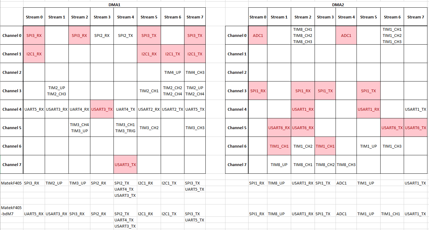
Finally, here is the table I made to visualize the DMA stream assignments, with the assignments for the MatekF405 target and my new target (which I called MatekF405-bdM7). Duplicate resources are highlighted. My approach was to first assign the required resources that are only available on a single stream (eg SPIx_RX, I2C), then the resources I wanted to add (eg USART3_RX), then try to make the remaining assignments work minimizing the number of TIMx_UP resources I had to disable.


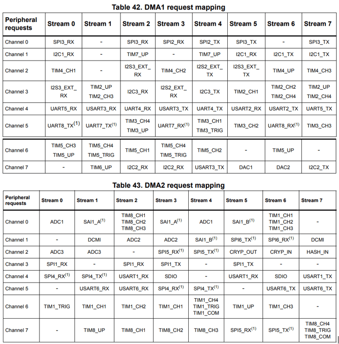
Simplified DMA Resources Table for STM32F4xx MCUs

Looks like it might work!

1 Like

Compiled, flashed, and bench tested. All looks good! I’m getting RPM from the ESC, and GPS and telemetry links on UARTs with DMA are working.

I also flashed a version of Bluejay on my BLHeli_S ESC that disables braking so the prop can freewheel, and that works well. I did find that DSHOT600 works more reliably than DSHOT300, and DSHOT150 doesn’t seem to work at all (using sched loop rate of 200 and dshot rate of 10).

Are there any more rigorous checks I can run before a flight test? Besides hwdef.h, is there another way I can verify DMA is working properly on the newly enabled UARTs?

in mavproxy:

ftp get @SYS/uarts.txt -

Will show you uart status - a ‘*’ indicates DMA

Hmm, no DMA on UART3_TX or UART5_TX. Should I make the following change?

- DMA_PRIORITY USART3_RX UART5_RX 
+ DMA_PRIORITY USART3* UART5*
Getting @SYS/uarts.txt as -
UARTV1
SERIAL0 OTG1  TX =  338159 RX =    2535 TXBD= 30598 RXBD=   229
SERIAL1 UART3 TX =  173960 RX*=       0 TXBD= 15740 RXBD=     0
SERIAL2 UART4 TX =   80674 RX =       0 TXBD=  7299 RXBD=     0
SERIAL3 UART1 TX*=     334 RX*=       0 TXBD=    30 RXBD=     0
SERIAL4 UART5 TX =  173944 RX*=       0 TXBD= 15739 RXBD=     0
SERIAL5 UART2 TX =       0 RX =       0 TXBD=     0 RXBD=     0

Edit: Appears to be a conflict between SPI3_TX and UART5_TX on DMA1 Stream 7. It doesn’t look like it’s possible to resolve since moving SPI3_TX to it’s alternate stream would trigger a series of changes that conflict with UART5_RX having it’s own stream. Back to the drawing board!

Edit2: Resolved, see below.