Help in creating rover

Hello, I have not been able to assemble a rover for 1 month
I will explain the whole situation: my supervisor instructed me to assemble a rover on the remote control. I began to study articles on the subject and follow the step by step instructions, but because I do not understand (or do not understand at all) what I do, I do not get anything (a normal explanation of the meaning of steps I have not found). I reread hundreds of times guide, watching training videos but they are always something missed or not given due attention (in the calculation that it is already clear), but I do not understand! Also, I got someone else, old PixHawk and I do not know what was it before me, but it periodically breaks without reason. I’m already tired of struggling with it, because I really want to learn how to build a Rover by myself, but the whole situation takes me out of force. So please, knowledgeable people help me!!!
About what I use:
RadioLink at10 remote control
RadioLink r12ds receiver
PixHawk 2.4.8 (with official Rover firmware v4.2.3)
Driver zd-5ad(I will attach the truth table)
Case from a machine consisting of two 9 V brush motors(one of which turns the wheels and the other is the rear drive)
I need it to be controlled by remote control with two channels (one responsible for forward and backward, the other for the right-left)
And one more question in the servo output there are different functions but it is not clear to me what they do and how to control them.Also I would really like to know how to link functions and rs channels.


here’s the principle of the swivel mechanism and if you power it too long, it will fly out of the slot and it can’t swivel anymore

Hi,

I doubt you will get a working rover with the parts you have.

  1. That motor controller does not work with ardurover, at least not without a lua script perhaps.

  2. Ardurover needs a proportional steering control. It is hard to tell from the pictures, but it looks like there is no feedback from the steering position to the motor. This will not work.

  3. Read and follow the ardurover documentation:

https://ardupilot.org/rover/

Do you know how to control two functions with one channel (I mean through the right stick (which is the default function Throttle))? I just need to give different digital signals for different outputs (i.e. for one output there will be 1, and the other 0. In the middle for both outputs should be 0 and 0. At the bottom of the turn 0 for one and 1 for another)

Ardurover does not work with on/off motor control. It needs to be able to control the rovers speed.
It looks like you can use a PWM signal to control the motor driver, but it uses one pin for the forward signal and one for reverse. Ardupilot uses a PWM signal from ca. 1000us to 2000us for direction and speed. So 1500us -2000us is forward and 1500us - 1000us is reverse. You could use an external microcontroller like an arduino to translate that signal or write a lua script running on the Pixhawk to generate the needed signal on two servo outputs.

I found today how to control the motor: aux outputs and a relay function for the digital signal
(and yes you are right my driver is not able to sense the PWM signal )

The ZK-5AD can take a PWM input signal:

Controlling it with aux pins in relay mode will not help you, as ardurover will have no way to know what to do with those outputs.

The pwm on that controller (0-100%) isn’t compatible with the pwm from the fc, (1000-2000us)

If you want the rover to work on ardurover, use hobby rc servos and rc esc motor controllers (brushed or brushless are available)

1 Like

Yes, that might be the another problem. As I wrote in my first post, I doubt that this hardware will result in a working rover.

Okay, I get it, but what about the table and how do I get the same result? What settings do I need to change to output these values to the two outputs?

About the table? Well this is how it is,
Using that motor controller you CAN NOT get variable speed control out with a flight controller. Which means it wont be able to work properly.
The way a flight controller works is a whole heap of control loops trying to keep variables at setpoints using proportional outputs.

If you want to use ardupilot for a rover it must start with a hobby (1000-2000us pwm) esc (not a 0-100% pwm motor controller like you have)
And a servo for steering, or two escs for left and right differerential wheel control.

Hello.Do you know how to control two functions with one channel (I mean through the right stick (which by default is the Throttle function and is controlled by my 3 rc channel))? I just need to feed different digital signals to different outputs (i.e. one output will have 1 and the other will have 0. The middle for both outputs should be 0 and 0. The bottom of the turn is 0 for one and 1 for the other)
P. S this is necessary to control the driver which needs to supply a signal to the two pins(I use the AT-10 remote control from Radiolink) (изменено)

There are only so many ways to tell you the same thing: Ardurover will not work with digital control!
The only way to make it work will be to put an arduino in between to translate the RC PWM to full range PWM on two pins. I did this years ago with an H-bridge motor controller.
This will still leave the issue with steering, which will also not work with digital control. You will need a servo for steering.

I’ll try and say it in a different way, but it’s really just repeating the same answers you’ve already received.

The vehicle you have chosen is ill suited to ArduPilot. That doesn’t change no matter how many times you ask on various media platforms.

As Count says, you could put an Arduino in between the autopilot and the vehicle’s electronics, but I think that will invite more frustration than success based on your inquiries so far.

I did what I wanted using STM32 and I recommend it (I could have done it before, but I only wanted to use PixHawk)

Hello,

It might be a bit late but I faced the same issue as you and I managed to get my rover working with a ZK-5AD and a Pixhawk 2.4.8. (though it also works for other Pixhawk versions like Pixhawk 6X). It does require a bit of work, but it’s within anyone’s reach. You just need to create a new mode which you could call, for example, ZK-5AD. Here you can find information on creating a mode in ArduPilot: Rover: Adding a New Drive Mode — Dev documentation. However, be careful with Mission Planner, the information is not up to date. You should not modify the ParameterMetaDataBackup.xml file but the rover.apm.pdef.xml file. I’ve made a comment about this on a forum: New Flight Mode not shown in Mission Planner - #17 by sylv.
Once all this is done, you just need to create a file that will be your new mode (e.g., mode_ZK5AD.cpp)
#include “Rover.h”

void ModeZK5AD::update() {

// fetch roll and pitch inputs
int16_t roll_out = RC_Channels::rc_channel(0)->get_radio_in();
int16_t pitch_out = RC_Channels::rc_channel(1)->get_radio_in();

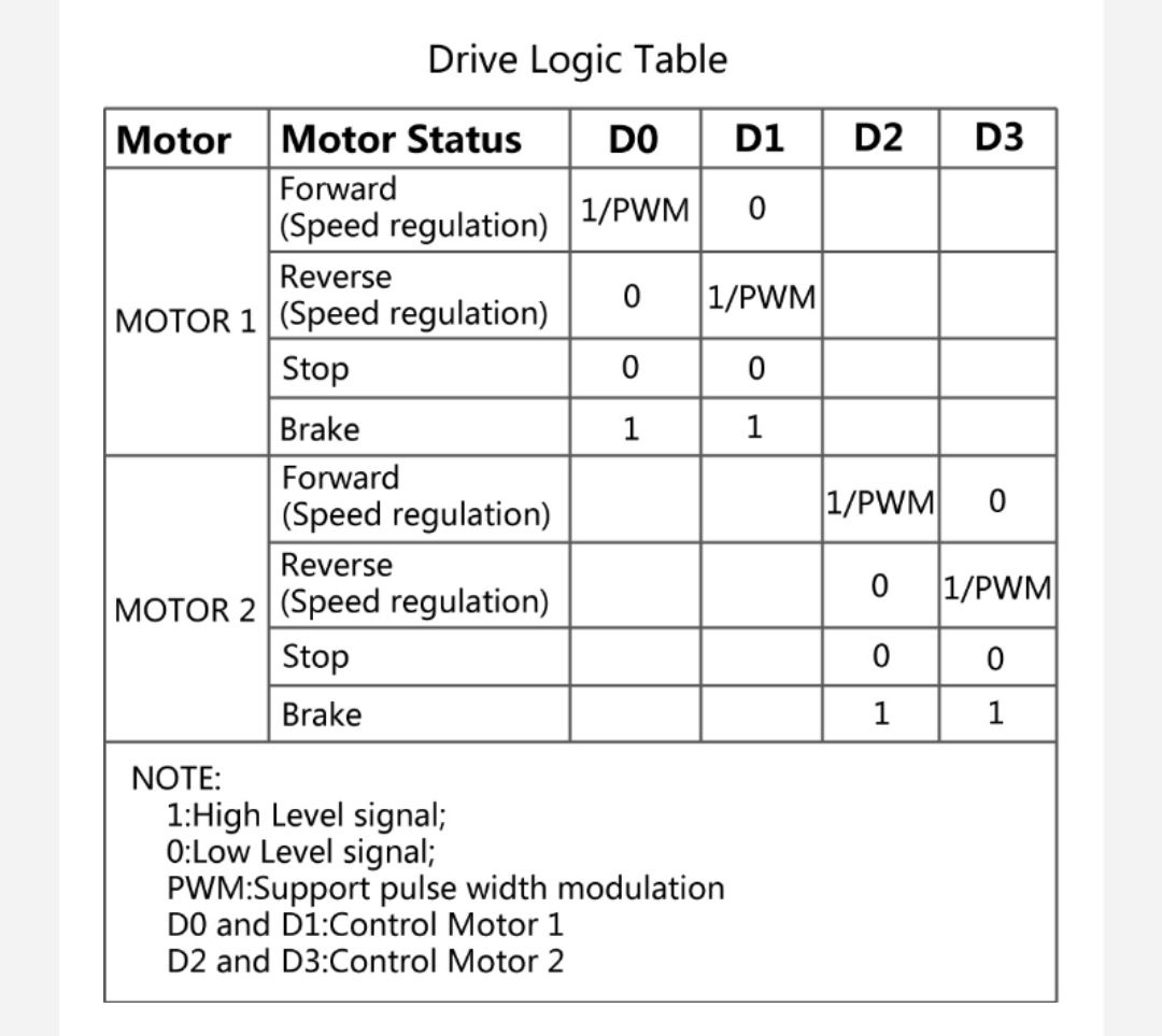
 // ZK-5AD Drive Logic Table  
if (pitch_out > 1500 + _TRIM) { // MOVE FORWARD
    GCS_SEND_TEXT(MAV_SEVERITY_INFO, "MOVE FORWARD");
    SRV_Channels::set_output_pwm_chan(_AUX_OUT1 ,_HIGH); //AUX_OUT1
    SRV_Channels::set_output_pwm_chan(_AUX_OUT2, _LOW);//AUX_OUT2
    SRV_Channels::set_output_pwm_chan(_AUX_OUT3, _HIGH); //AUX_OUT3
    SRV_Channels::set_output_pwm_chan(_AUX_OUT4, _LOW); //AUX_OUT4
} else if (pitch_out < 1500 - _TRIM) { // MOVE BACK
    GCS_SEND_TEXT(MAV_SEVERITY_INFO, "MOVE BACK");
    SRV_Channels::set_output_pwm_chan(_AUX_OUT1, _LOW);
    SRV_Channels::set_output_pwm_chan(_AUX_OUT2, _HIGH);
    SRV_Channels::set_output_pwm_chan(_AUX_OUT3, _LOW);
    SRV_Channels::set_output_pwm_chan(_AUX_OUT4, _HIGH);
} else if (abs(pitch_out - 1500) <= _TRIM) { // TURN RIGHT
    if (roll_out > 1500 + _TRIM) {
        GCS_SEND_TEXT(MAV_SEVERITY_INFO, "TURN RIGHT");
        SRV_Channels::set_output_pwm_chan(_AUX_OUT1, _LOW);
        SRV_Channels::set_output_pwm_chan(_AUX_OUT2, _HIGH);
        SRV_Channels::set_output_pwm_chan(_AUX_OUT3, _HIGH);
        SRV_Channels::set_output_pwm_chan(_AUX_OUT4, _LOW);
    } else if (roll_out < 1500 - _TRIM) { // TURN LEFT
        GCS_SEND_TEXT(MAV_SEVERITY_INFO, "TURN LEFT");
        SRV_Channels::set_output_pwm_chan(_AUX_OUT1, _HIGH);
        SRV_Channels::set_output_pwm_chan(_AUX_OUT2, _LOW);
        SRV_Channels::set_output_pwm_chan(_AUX_OUT3, _LOW);
        SRV_Channels::set_output_pwm_chan(_AUX_OUT4, _HIGH);
    } else { // STOP
        GCS_SEND_TEXT(MAV_SEVERITY_INFO, "STOP");
        SRV_Channels::set_output_pwm_chan(_AUX_OUT1, _LOW);
        SRV_Channels::set_output_pwm_chan(_AUX_OUT2, _LOW);
        SRV_Channels::set_output_pwm_chan(_AUX_OUT3, _LOW);
        SRV_Channels::set_output_pwm_chan(_AUX_OUT4, _LOW);
    }

}

}

And in the mode.h file, you can declare the class as follows:

class ModeZK5AD : public Mode {

public:

uint32_t mode_number() const override {
    return ZK5AD;
}
const char *name4() const override {
    return "ZK5AD";
}

// methods that affect movement of the vehicle in this mode
void update() override;

private:
// constants
const int _HIGH = 2000;
const int _LOW = 1000;
const int _TRIM = 10;
const int _AUX_OUT1 = 8;
const int _AUX_OUT2 = 9;
const int _AUX_OUT3 = 10;
const int _AUX_OUT4 = 11;
};

The D0, D1, D2, and D3 inputs of the ZK-5AD are connected respectively to the AUX_OUT1, AUX_OUT2, AUX_OUT3, and AUX_OUT4 signal line outputs of the Pixhawk. Make sure to also connect the ground lines.
The last very important thing to do is to change the SERVO_RATE parameter value. By default, it’s set to 50Hz with the Rover, but the output signal is too weak to control the ZK-5AD driver card. You need to change the value from 50 to 400. As a result, your output voltage will change from 0.25V to 2.65V. (because it’s a PWM signal). You can do it with mission planner software in config menu->full parameter list.( For information 400Hz is the frequency used in copter firmware.)

With this, the rover should move as expected, without changing the rest of the code or the hardware.

Remember to test everything in a controlled environment and ensure that you have emergency stop capabilities to prevent any accidents. I hope this helps and that you can get your rover going without much trouble!

Good luck with your project!

Okay, this is a much improved method—I apologize for the oversight in the previous attempt. :worried: It would be more efficient to configure your channels with the relay function to use them as digital outputs.

To achieve this, you can modify the previous code as follows:
mode_ZK5AD.cpp :

#include “Rover.h”

void ModeZK5AD::setRoverMovement(RoverMovement movement) {
const char* message = nullptr;
switch (movement) {
case RoverMovement::MoveForward:
message = “MOVE FORWARD”;
ap_relay->on(0);
ap_relay->off(1);
ap_relay->on(2);
ap_relay->off(3);
break;
case RoverMovement::MoveBack:
message = “MOVE BACK”;
ap_relay->off(0);
ap_relay->on(1);
ap_relay->off(2);
ap_relay->on(3);
break;
case RoverMovement::TurnRight:
message = “TURN RIGHT”;
ap_relay->off(0);
ap_relay->on(1);
ap_relay->on(2);
ap_relay->off(3);
break;
case RoverMovement::TurnLeft:
message = “TURN LEFT”;
ap_relay->on(0);
ap_relay->off(1);
ap_relay->off(2);
ap_relay->on(3);
break;
case RoverMovement::Stop:
message = “STOP”;
ap_relay->off(0);
ap_relay->off(1);
ap_relay->off(2);
ap_relay->off(3);
break;
}
if (message) {
GCS_SEND_TEXT(MAV_SEVERITY_INFO, “%s”, message);
}

}
void ModeZK5AD::update() {

// Exit immediately if no relay is setup
if (!ap_relay) {
    return;
}
int16_t roll_out = RC_Channels::rc_channel(0)->get_radio_in();
int16_t pitch_out = RC_Channels::rc_channel(1)->get_radio_in();


// Make movement decisions based on pitch and roll
if (pitch_out > CENTER_PWM + _TRIM) {
    setRoverMovement(RoverMovement::MoveForward);
} else if (pitch_out < CENTER_PWM - _TRIM) {
    setRoverMovement(RoverMovement::MoveBack);
} else if (abs(pitch_out - CENTER_PWM) <= _TRIM) {
    if (roll_out > CENTER_PWM + _TRIM) {
        setRoverMovement(RoverMovement::TurnRight);
    } else if (roll_out < CENTER_PWM - _TRIM) {
        setRoverMovement(RoverMovement::TurnLeft);
    } else {
        setRoverMovement(RoverMovement::Stop);
    }
}

}

mode.h :
class ModeZK5AD : public Mode {

public:

uint32_t mode_number() const override {
    return ZK5AD;
}
const char *name4() const override {
    return "ZK5AD";
}

// methods that affect movement of the vehicle in this mode
void update() override;

private:

static constexpr int16_t CENTER_PWM = 1500;
AP_Relay *ap_relay = AP::relay();
int16_t _TRIM = 10;

enum class RoverMovement {
    MoveForward,
    MoveBack,
    TurnRight,
    TurnLeft,
    Stop
};

Please review the code for any errors.

With mission planner, go to setup-> servo output and set channels 9,10,11,12 as GPIO.

In config menu-> standard parameters , activate the relay as shown :

You will no longer need to adjust SERVO_RATE, and you’ll achieve a 3.3V output. This approach should be much more effective.