Help debugging setting VTX Power via SmartAudio? Debug logs included

As reported previously I’m having issues with setting VTX power via SmartAudio on a Rush Ultimate Plus. The FC is a Matek H743. The SmartAudio is wire is connected to Tx3 on the FC which corresponds to SERIAL4.

Settings are:
VTX_ENABLE=1
VTX_OPTIONS=0 (also tested with 8, 16, and 24)
SERIAL4_PROTOCOL=37
SERIAL4_BAUD=4
SERIAL4_OPTIONS=4 (also tried it with 68)

I modified the SmartAudio code to send debug messages via MAVLink rather than via the console (since that was all mixed up with the MAVLink messages on the console). I’ve included the full logs below (in reverse chronological order), this includes an attempt to change VTX_POWER via the full parameter list in Mission Planner that doesn’t show up at all in the debug messages.

Anyone have any suggestions on what might be the problem?

messages.txt (19.1 KB)

There is no recognizable response coming back so it keeps autobauding. One thing you could try is the inav bug - set stops bits to 1 in the code and see if that helps (some VTX’s have a broken implementation because iNav had a broken implementation which they copied)

I added some more debug logs and got the following (reading bottom to top):

5/13/2022 8:49:53 PM : SA: incoming_bytes_count: 1, response_header_size: 4
5/13/2022 8:49:53 PM : SA: incoming_bytes_count < response_header_size && _inline_buffer_length == 0

5/13/2022 8:49:53 PM : SA: read_response()

5/13/2022 8:49:53 PM : SA: incoming_bytes_count: 1, response_header_size: 4
5/13/2022 8:49:53 PM : SA: incoming_bytes_count < response_header_size && _inline_buffer_length == 0
5/13/2022 8:49:53 PM : SA: read_response()

It’s like it only ever sees one incoming byte in the response. This is with VTX_OPTIONS=16 and SERIAL4_OPTIONS=4.

Just for fun I flashed with INAV and was able to set the VTX power levels 1-4, though I wasn’t able to figure out how to get it out of pit mode programmatically (had to do that manually). So I know the wiring is good at least.

So this is really weird. As I mentioned I was able to set VTX power levels in INAV with the same hardware, but I’ve had no luck with ArduPlane.

I’ve tried VTX_OPTIONS set to 0 and 16
I’ve tried SERIAL4_OPTIONS set to 4 and 68
I’ve tried using Tx4 (which maps to SERIAL6 on this hardware) and updating all the SERIAL4 and SERIAL6 options appropriately.
I’ve tried wiping all config options back to default and only configuring VTX_OPTIONS and the SERIAL6 options.

In all cases ArduPlane is only ever seeing a single byte in read_reponse() when it’s expecting at least the 4 bytes of the header.

Others have reported success with Matek 405 boards and the Rush Tank Ultimate, while I’m using the H743 and Rush Tank Ultimate Plus. But I’m having no luck.

Try setting stops bits to 1. This is how iNav used to work (which is a bug, SA is 2 stop bits)

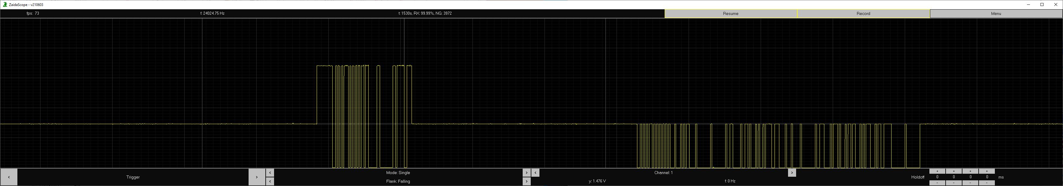
I rigged up an Arduino Nano to act as a crude oscilloscope sampling at 24KHz and I got the following trace (zipped excel file included):

smartaudio_debug.zip (146.7 KB)

The first thing I note is that the “high” signal coming from the VTX is only about 1.5V. This is below the standard 2V cutoff for 3.3V logic, but is within the 0.9-3.3V range specified by the SmartAudio spec. Is it possible that my flight controller is simply not recognizing this as a valid signal because the levels are too low? Should I set the “RX pull-up” bit in the serial options?

The shortest high and low intervals are about 0.0208 msec which is what you’d expect from a 4800 baud signal. This signal corresponds to the request_setting() routine so it should consist of 0xAA 0x55 0x03 0x00 0x9F which checks out given that each byte is sent LSB first.

Comparing this to the “get settings” example in https://www.team-blacksheep.com/tbs_smartaudio_rev09.pdf the signal sent from the FC looks good. If we look at the signal coming back from the VTX (and this is easier to see in the spreadsheet charts) we see that it doesn’t match. It looks like it’s using one stop bit instead of two, with that the response is:

AA 55 11 0D 00 00 06 16 E9 07 04 00 0E 17 1B 1D F3 00 00

The first two bytes are fine, the next byte indicates a SmartAudio 2.1 response. The next byte is the length, which matches up with having 5 total power levels (4 plus pit mode), then operation mode (pitmode running, using in-range pitmode), then frequency, then 5 power levels that match up with the advertised ones (in dB its 0/14/23/27/29, in mW it’s 0/25/300/500/800), then a CRC and two bytes of zeros. So as far as I can tell this is a valid response except for the fact that it’s using one stop bit instead of two.

I modified Arduplane to use 1 stop bit (confirmed in the scope trace). The VTX still responded with the same response, but oddly ArduPlane is still reporting an “incoming_bytes_count” of 1 instead of at least the 4 bytes of the header, even though on the scope trace the signal looks okay. So I’m not sure what’s going on there.

Strangely, I still get an “incoming_bytes_count” of 1 even if the VTX is powered off, which seems a little odd.