Hi Chris,
i tested 3.6.5 version but don´t find H_RSC_GOV_SET parameter and others.
What version have all governor parameters included?
With all the new features on this release cycle there was getting to be too many builds for each feature. So I consolidated these things and reduced the number of builds to two for 3.6 and one for 3.5. You can pick which one you want to test - all them have the governor.
Also note that in the final version that will be in 3.7-Dev the names of two parameters for the governor will be changed. The H_RSC_GOV_SET becomes H_RSC_HEADSPEED and the governor TC becomes TCGAIN. These changes are not reflected in the ArduHeli 3.6.9 build that has every feature we’ve developed in it.
The descriptions for these settings do not yet appear in any of the ground stations. But they are on the wiki now in the parameter descriptions.
This version also have four-servo support?
Yes, the 3.6.9 build has four-servo, governor, L1 Nav, virtual flybar acro. Due to the way the servos and swashplate is handled you will have to verify that all your settings for head and cyclic servos are correct before flying. There is a short summary there on the download page that explains the settings.
Awesome @ChrisOlson👍🏻 I’ve been on a Gasser Build for Agriculture Mission and your work here is so much helpful to me! Thank you!
Please Chris, tell me page link for download 3.6.9 version and summary explains settings.
It is in the link 4 posts above. Just scroll down to the 3.6.9 build.
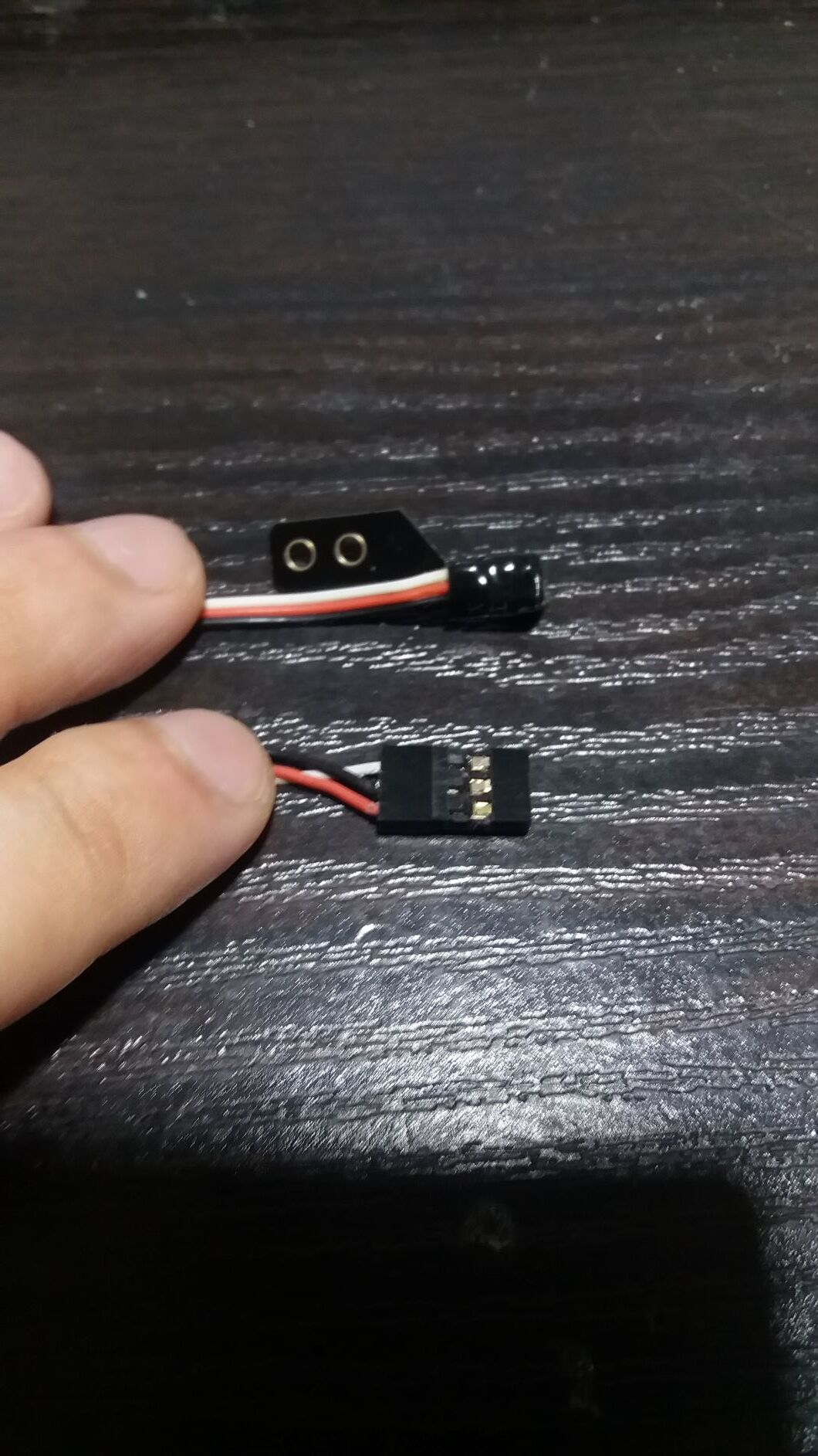
I am assembling an electric 450 helicopter with a Micro Pix controller, but I have problems with the software governor described here.
For heli version 4.0 an Incorporated a rotor speed governor seems extremely interesting. Not having yet the required RPM sensor I first simulated it with a servo tester on a poorly configured Pixhawk with V4.0.0-rc2 firmware. It works immediately as described here, without arming or safety switch:
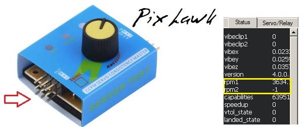
(Mission Planner, Flight Data, Status)
Since the servo tester should generate a PWM pulse at 50 to 60 Hz (compatible with analog servos, 3000 to 3600 rpm) 3634 as shown for rpm1 makes sense. If disconnecting the servo tester rpm1 becomes -1.
But the Micro Pix has no AUX pins, but pins equivalent to the MAIN ones on the Pixhawk. PWM1 to PWM5 are connected to four servos and the ESC and work (BRD_PWM_COUNT=5). So one in PWM6/7/8 (or SBUS (unused)) should be defined as input in the code, and have code to implement timing to get rpm.
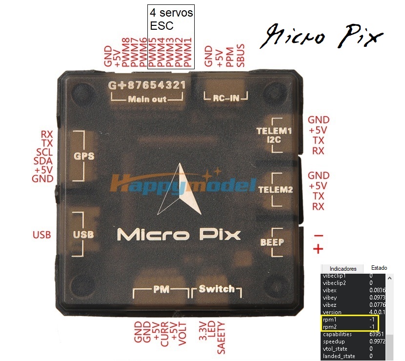
Not having examined the sources and not having the schematic, I don’t know if this is contemplated. After several trials (changing BRD_PWM_COUNT, RPM_PIN and SERVO6/7/8_FUNCTION) I get always -1 on rpm1 and rpm2 and messages “Cannot attach to pin xx”.
Is it possible to have rpm input on a Micro Pix controller?
If so, how?
Thanks.
It is not possible to have a RPM input on a mini-controller that does not have aux pins.
Actually it should be, as the aux pins are the fmu pins: which are main on a flight controller without an iomcu.
I wonder the use of these input meaning values:
51 RCIN1
52 RCIN2
53 RCIN3
54 RCIN4
55 RCIN5
56 RCIN6
57 RCIN7
58 RCIN8
59 RCIN9
60 RCIN10
61 RCIN11
62 RCIN12
63 RCIN13
64 RCIN14
65 RCIN15
66 RCIN16
on
SERVOxx_FUNCTION: Servo output function
parameters.
What are they meant for?
On Pixhawk schematics sheet 9/12 (Servo Header/S.Bus interface) pins labelled J901-31 to J901-46 (6 AUX) finish in FMU CH6 to CH1, as you say (FMU microprocessor pins PD14, PD13,PE9, PE11, PE13 and PE14).
Pins labelled J901-7 to J901-28 (8 MAIN) finish in IO CH8 to CH1 (IOMCU).
But I have no Micro Pix schematics and cannot find these equivalent connections por Micro PIX PWM1 to PWM8.
So you can pass any input directly through to any output
Ports 1 thru 4 are used for servos, 8 is throttle. That leaves either 5 , 6 or 7 that have to be defined as aux for rpm input. Not sure how to do that on a mini-controller.
“So you can pass any input directly through to any output”
Yes, assigning
SERVO5_FUNCTION = SERVO6_FUNCTION = 56 (RCIN6)
makes transmitter CH6 appear on PWM5 and PWM6.
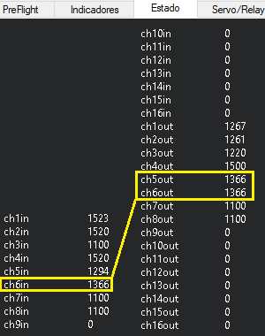
A servo on Micro Pix PWM6 (where I had connected above the servo tester) can be moved with transmitter CH6.
If switching off the transmitter, the receiver failsafe value appears on CH5OUT and CH6OUT.
Dear Chris Ohlson,
After a long search I think I’ve now found what I need with your governor.
However… I’m a complete newbie to ArduPilot.
It looks somewhat like opent, but then for flightcontrollers.
If I understand your post correctly, correct me if I’m wrong,
-study this post carefully
- I need to buy an ArduPilot unit (not Arduino I guess)
- upload your most recent software to it
- connect the system with receiver and turbine (a Viehauser two stage turbine, consisting of a Frank tj67 and a n2 stage for driving the rotor)
- mount a magnet on the main stage (rotating at rotorspeed, max 950rpm)
- mount a hall sensor
Connect everything, making sure that the throttle curve is correct and I would have a governed helicopter, right?
I only need it for governing rotor rpm, not for other functions
So setup would be easy I guess
Hi Pieter,
This is mostly correct.
The throttle curve is only part of the calculation and the governor will use it for fallback if your speed sensor fails in flight. So having a properly tuned throttle curve is important. But the actual governor itself is separate settings. The governor constantly tracks the throttle curve and uses it for making its calculations for throttle control. The governor will correct for changes in density altitude and maintain the headspeed without having to re-tune the throttle curve all the time.
We have flown it with a Solar T62 2A1 engine, 95shp. The T62 is basically the APU engine from a UH-60 Blackhawk helicopter, modified with a N2 power section. So very similar to your TJ67, although quite a bit larger. The T62 does not have a FADEC. It has a FCU like a Pratt & Whitney PT6 or Garrett TPE331.
You will need some modifications I have made in a custom build in order to start and fly that engine.
Coordinate with @bnsgeyer to determine if he wants to modify the ArduPilot code to start and run one of those, or if he thinks it would be better to use my custom build that fully supports turbine engines.
I’d like to stress that ArduPilot focuses on fully autonomous stuff. Which is practical with electric-powered helicopters. But once you move to piston or turbine power, it requires many of the same procedures as any full-size helicopter to get one into the air, and operate it, without experiencing engine failure or crashing it.
So ArduPilot has focused mainly on electric, limited support for piston, zero support for turbine. But in larger helicopters turbine power is very common because no other engine produces the shaft horsepower of a turboshaft at the same power/weight ratio.
So support for turbine power has been neglected. It is one of those deals where “Build it and they will come, Ray”.
Thanks a lot!!!
Yeah… turbine power is great.
But, do I understand it correctly that it could be usable on a RC helicopter
Gascurve is challenging since you have a start up range and an operating range for these type of engines
The relatively low rotor rpm of 800 - max 950 does not pose a problem? Or should I try to magnets to increase the pulse rate from 1700-1900 rpm?
I will follow your suggestion and contact him as well
Yes, I understand the challenge of operating turbines. I have way more turbine time in my aviation career than I do piston time 
This is why you will need my advanced throttle controls to operate it. It is up to Bill if he wants to put that into ArduPilot or not.
That rpm is not a problem. Use four magnets on the auto gear to increase the number of samples for the speed sensor and it will be fine. The sensor value is scaled, so if you use four magnets, set the scale to 0.25 and it will return actual rotor rpm. The more pulses you have, the better the mode filter is at giving you an accurate rpm input to the control.