It depends on the engine and throttle linkage geometry. I have a 23-35-47-61-100 in a helicopter with a 310 engine. Same model of helicopter with a 290 engine I use 18-25-37-60-100
Thanks Chris …
Hi Chris! Been working with Frank on installing this system onto one of our birds. We’re using a Stator Gator sensor, sending the signal from the engine for RPM control.
But this article is stating that he should be measuring ROTOR RPM. Can you clarify?
Hi Chris,
Yes, it is a rotor speed governor, not engine speed. But assuming you can get the Stator Gator signal into the controller’s RPM input and read it, the governor will work using engine speed. But you’ll have to use this code -> if Frank wants to build himself.
That has the latest changes that allow setting the governor range. So, say for instance, you are running 1,200 rpm headspeed you would want to the governor to come in (usually) at 90% N2, so the range would be set to 120 rpm so the governor comes on at 1,080 rpm.
If you’re measuring engine speed with a 7:1 gear ratio, then governed speed with the same headspeed would be 8,400 rpm. Now, for the same range of rotor speed regulation you need 10% of 8,400, which is 840. So the range would have to be set 840 to get the same result for governor engage.
So the code in the above link has this latest change that lets you set the range, the previous build didn’t have that, so wouldn’t work when measuring engine rpm instead of rotor rpm.
Frank is flying either a Navio or Navio2, can’t remember which he said when I talked to him on the phone. So I just added builds for both those boards on the build page to save him having to build it himself. You can get them here ->
Let me know if you get the Stator Gator signal to work with the rpm input on the controller. I’ve never tried that before, but it’s the same as a hall effect so it should work.
Hi Chris, is possible to add gear ratio like GV-1
It’s certainly possible, but not practical. The GV-1 was never designed for UAV use. This is a N2 governor planned to be integrated with autorotation features. ERPM tells us nothing about monitoring the system to detect drivetrain failure and managing collective to maintain RRPM in autorotation.
You can scale the RPM value with RPM_SCALING.
Great, Hi Chris … is your code work with scaling value on RPM
Yes. The two functions, governor and rpm, are separate in the code. The governor will use whatever values come from the RPM feature.
The normal use of the scaling would be, for instance, where you have 2 magnets on your rotating component. If that component is turning at 1,000 rpm, it will show 2,000 rpm because it’s measuring 2 pulses/rev. So set the scaling to 0.5 to get the real rpm value.
with one magnet attached on to engine rotating component, value of scaling rpm would be 1/gear ratio, is correct ?
If you want to read or display relative rotor rpm instead of engine rpm, yes. But in reality it’s just as easy to put the magnet and sensor on the part you want to measure. These little $11 hall effect sensors work fine and don’t require tying anything into the magneto primary like a stator gator does.
https://www.amainhobbies.com/align-beastx-plus-governor-sensor-agnhegbp001/p505962
Great, thanks chris …
请教fubaba cgy750 定速 GV-1传感器可以用到 pix4 上吗? 谢谢
我把fubaba cgy750 定速传感器,接到第五通道,没有转速显示出来 ,是不是哪里没设置好 ,还是传感器不匹配。
Can Fubaba cgy750 speed sensor be used on pix4? Thank you
I connected the Fubaba cgy750 constant speed sensor to the fifth channel and did not show the speed. Is it not set up or the sensor does not match?
I don’t know for sure. That’s a backplate sensor for nitro engines. I’m not sure if it puts out the correct signal or not.
好的 明白谢谢 那我买个 [AGNHEGBP001] 传感器回来试下 ,非常感谢你的回复。
Okay, thank you. I’ll buy a [AGNHEGBP001] sensor and try it back. Thank you very much for your reply.
你好 ChrisOlson
我买回来了[AGNHEGBP001],接上去 还是没有转速出来。是我哪里没有设置好呢? 转速哪里就是现实:-1
Hello ChrisOlson
I bought it back [AGNHEGBP001], and it still didn’t rotate. Where did I not set it up? Where speed is reality: - 1
I’m not sure what you’re saying? Are you saying you get no rpm reading?
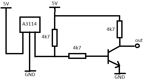
Hi, just tried with GV-1 sensor, GV-1 sensor use analog type sensor, so you need some conversion to use with pixhawk. futaba sensor use different polarization of magnet, I think it North. I’ve made sensor with A3114 hall effect sensor, a couple resistor and transistor for reverse the output from sensor. It working now

Dear Chris,
I have tried using the Align hall effect sensor with the provided magnets and works perfectly with px4 flightstack. I recently moved to Arducopter for the exact same setup and the rpm just refuses to register on the topic “rpm1” when I am checking on Mission Planner. I am using the latest v3.6.9 from your forked repo.
Any help would be appreciated! Thanks.
For a board with 6 aux outputs make sure the board pwm count is set to 4 and the relay pin and rpm settings are what is shown in the screenshots in the post at the beginning of this thread.