Helicopter Rotor Speed Governor

请教fubaba cgy750 定速 GV-1传感器可以用到 pix4 上吗? 谢谢

我把fubaba cgy750 定速传感器,接到第五通道,没有转速显示出来 ,是不是哪里没设置好 ,还是传感器不匹配。

Can Fubaba cgy750 speed sensor be used on pix4? Thank you

I connected the Fubaba cgy750 constant speed sensor to the fifth channel and did not show the speed. Is it not set up or the sensor does not match?

I don’t know for sure. That’s a backplate sensor for nitro engines. I’m not sure if it puts out the correct signal or not.

好的 明白谢谢 那我买个 [AGNHEGBP001] 传感器回来试下 ,非常感谢你的回复。

Okay, thank you. I’ll buy a [AGNHEGBP001] sensor and try it back. Thank you very much for your reply.

你好 ChrisOlson
我买回来了[AGNHEGBP001],接上去 还是没有转速出来。是我哪里没有设置好呢? 转速哪里就是现实:-1

Hello ChrisOlson

I bought it back [AGNHEGBP001], and it still didn’t rotate. Where did I not set it up? Where speed is reality: - 1

I’m not sure what you’re saying? Are you saying you get no rpm reading?

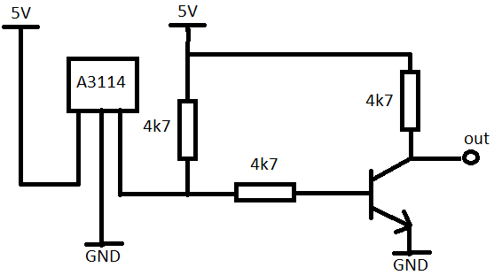
Hi, just tried with GV-1 sensor, GV-1 sensor use analog type sensor, so you need some conversion to use with pixhawk. futaba sensor use different polarization of magnet, I think it North. I’ve made sensor with A3114 hall effect sensor, a couple resistor and transistor for reverse the output from sensor. It working now

hall%20effect

Dear Chris,

I have tried using the Align hall effect sensor with the provided magnets and works perfectly with px4 flightstack. I recently moved to Arducopter for the exact same setup and the rpm just refuses to register on the topic “rpm1” when I am checking on Mission Planner. I am using the latest v3.6.9 from your forked repo.

Any help would be appreciated! Thanks.

For a board with 6 aux outputs make sure the board pwm count is set to 4 and the relay pin and rpm settings are what is shown in the screenshots in the post at the beginning of this thread.


hi chris,
is that the correct wire sequence for the AGNHEGBP001?

Hi Chris,
i tested 3.6.5 version but don´t find H_RSC_GOV_SET parameter and others.
What version have all governor parameters included?

With all the new features on this release cycle there was getting to be too many builds for each feature. So I consolidated these things and reduced the number of builds to two for 3.6 and one for 3.5. You can pick which one you want to test - all them have the governor.

Also note that in the final version that will be in 3.7-Dev the names of two parameters for the governor will be changed. The H_RSC_GOV_SET becomes H_RSC_HEADSPEED and the governor TC becomes TCGAIN. These changes are not reflected in the ArduHeli 3.6.9 build that has every feature we’ve developed in it.

The descriptions for these settings do not yet appear in any of the ground stations. But they are on the wiki now in the parameter descriptions.

http://ardupilot.org/copter/docs/parameters.html

This version also have four-servo support?

Yes, the 3.6.9 build has four-servo, governor, L1 Nav, virtual flybar acro. Due to the way the servos and swashplate is handled you will have to verify that all your settings for head and cyclic servos are correct before flying. There is a short summary there on the download page that explains the settings.

Awesome @ChrisOlson👍🏻 I’ve been on a Gasser Build for Agriculture Mission and your work here is so much helpful to me! Thank you!

Please Chris, tell me page link for download 3.6.9 version and summary explains settings.

It is in the link 4 posts above. Just scroll down to the 3.6.9 build.

I am assembling an electric 450 helicopter with a Micro Pix controller, but I have problems with the software governor described here.

For heli version 4.0 an Incorporated a rotor speed governor seems extremely interesting. Not having yet the required RPM sensor I first simulated it with a servo tester on a poorly configured Pixhawk with V4.0.0-rc2 firmware. It works immediately as described here, without arming or safety switch:
gov_pixhawk
(Mission Planner, Flight Data, Status)

Since the servo tester should generate a PWM pulse at 50 to 60 Hz (compatible with analog servos, 3000 to 3600 rpm) 3634 as shown for rpm1 makes sense. If disconnecting the servo tester rpm1 becomes -1.

But the Micro Pix has no AUX pins, but pins equivalent to the MAIN ones on the Pixhawk. PWM1 to PWM5 are connected to four servos and the ESC and work (BRD_PWM_COUNT=5). So one in PWM6/7/8 (or SBUS (unused)) should be defined as input in the code, and have code to implement timing to get rpm.


Not having examined the sources and not having the schematic, I don’t know if this is contemplated. After several trials (changing BRD_PWM_COUNT, RPM_PIN and SERVO6/7/8_FUNCTION) I get always -1 on rpm1 and rpm2 and messages “Cannot attach to pin xx”.

Is it possible to have rpm input on a Micro Pix controller?
If so, how?

Thanks.

It is not possible to have a RPM input on a mini-controller that does not have aux pins.

Actually it should be, as the aux pins are the fmu pins: which are main on a flight controller without an iomcu.

I wonder the use of these input meaning values:
51 RCIN1
52 RCIN2
53 RCIN3
54 RCIN4
55 RCIN5
56 RCIN6
57 RCIN7
58 RCIN8
59 RCIN9
60 RCIN10
61 RCIN11
62 RCIN12
63 RCIN13
64 RCIN14
65 RCIN15
66 RCIN16
on
SERVOxx_FUNCTION: Servo output function
parameters.

What are they meant for?

On Pixhawk schematics sheet 9/12 (Servo Header/S.Bus interface) pins labelled J901-31 to J901-46 (6 AUX) finish in FMU CH6 to CH1, as you say (FMU microprocessor pins PD14, PD13,PE9, PE11, PE13 and PE14).

Pins labelled J901-7 to J901-28 (8 MAIN) finish in IO CH8 to CH1 (IOMCU).

But I have no Micro Pix schematics and cannot find these equivalent connections por Micro PIX PWM1 to PWM8.