The binaries have been updated in the 3.6 Governor code to reflect a change I made to add a method of scheduling the gas generator in two-stage turbine engines. The link is in the first post in this thread.
It is a relatively minor change, but it does effectively double the available governor output in the normal operational range to schedule the gas generator to meet N2 torque demand. This will change how the governor droop response setting is applied for piston engines. I flew it in two different piston machines, and both used a 55% governor droop setting after re-tuning.
I flew with a MW54 and 88% droop response worked nicely with the turbine.
The code is latest Copter 3.6.6 with the governor feature added to it. This feature is also now in PR for Copter 3.7 beta.
It depends on the engine and throttle linkage geometry. I have a 23-35-47-61-100 in a helicopter with a 310 engine. Same model of helicopter with a 290 engine I use 18-25-37-60-100
Hi Chris! Been working with Frank on installing this system onto one of our birds. We’re using a Stator Gator sensor, sending the signal from the engine for RPM control.
But this article is stating that he should be measuring ROTOR RPM. Can you clarify?
Hi Chris,
Yes, it is a rotor speed governor, not engine speed. But assuming you can get the Stator Gator signal into the controller’s RPM input and read it, the governor will work using engine speed. But you’ll have to use this code -> if Frank wants to build himself.
That has the latest changes that allow setting the governor range. So, say for instance, you are running 1,200 rpm headspeed you would want to the governor to come in (usually) at 90% N2, so the range would be set to 120 rpm so the governor comes on at 1,080 rpm.
If you’re measuring engine speed with a 7:1 gear ratio, then governed speed with the same headspeed would be 8,400 rpm. Now, for the same range of rotor speed regulation you need 10% of 8,400, which is 840. So the range would have to be set 840 to get the same result for governor engage.
So the code in the above link has this latest change that lets you set the range, the previous build didn’t have that, so wouldn’t work when measuring engine rpm instead of rotor rpm.
Frank is flying either a Navio or Navio2, can’t remember which he said when I talked to him on the phone. So I just added builds for both those boards on the build page to save him having to build it himself. You can get them here ->
Let me know if you get the Stator Gator signal to work with the rpm input on the controller. I’ve never tried that before, but it’s the same as a hall effect so it should work.
It’s certainly possible, but not practical. The GV-1 was never designed for UAV use. This is a N2 governor planned to be integrated with autorotation features. ERPM tells us nothing about monitoring the system to detect drivetrain failure and managing collective to maintain RRPM in autorotation.
Yes. The two functions, governor and rpm, are separate in the code. The governor will use whatever values come from the RPM feature.
The normal use of the scaling would be, for instance, where you have 2 magnets on your rotating component. If that component is turning at 1,000 rpm, it will show 2,000 rpm because it’s measuring 2 pulses/rev. So set the scaling to 0.5 to get the real rpm value.
If you want to read or display relative rotor rpm instead of engine rpm, yes. But in reality it’s just as easy to put the magnet and sensor on the part you want to measure. These little $11 hall effect sensors work fine and don’t require tying anything into the magneto primary like a stator gator does.
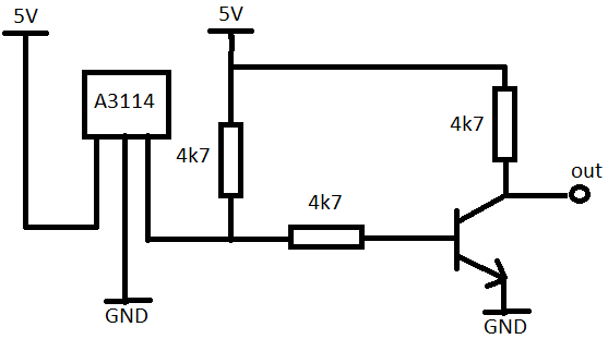
Hi, just tried with GV-1 sensor, GV-1 sensor use analog type sensor, so you need some conversion to use with pixhawk. futaba sensor use different polarization of magnet, I think it North. I’ve made sensor with A3114 hall effect sensor, a couple resistor and transistor for reverse the output from sensor. It working now