Thanks for the feedback on it. Yeah, everybody that has flown it so far likes how it comes in and works. It’s not a “sloppy” type thing where the pilot doesn’t know for sure if it’s working or not, and that’s the feedback I’ve gotten on it from other folks.
The build link posted above, built on 3.6.5rc2 should have the Bad Logging fix in it. That firmware has the slowdown setting for the SD card and is what I am currently flying. I will update those binaries, though, to the latest 3.6.5 release tonight and post a notice here that they are available for stable release users.
Just google for Align, Aerospire, or Spartan rpm sensor. Pick the one you want. Basically, any hall-effect sensor will work with a magnet on the main or autorotation gear.
So I put a soft-start feature in the heli governor. I did this primarily for turbines to prevent over-fueling the Ng and spiking the Turbine Inlet Temp beyond 1000C and burning up the power section when the governor comes on. It would make the N2 power turbine glow red with significant flame on the tailpipes.
But it works good for piston engines too. I uploaded new binaries that have this feature, and they are available in the link in the first post in this thread.
Little too cold here to mess with a kerostart turbine today, but this a demo with a piston heli.
In the process of looking through @ChrisOlson governor code, I got to thinking about how the controller could monitor the RPM. Not necessarily for governing the rotor but for determining the state of the rotor for the startup and shutdown part of the rotor speed controller (RSC). This idea was to replace the timers that are currently employed to determine the rotor has completed run up and is below the critical RPM. So my first thought was a FFT that was always running in the background but that sounded difficult cause I don’t know where there is an FFT library in ardupilot and probably a little computationally expensive. Also the measured rotor speed would have to probably lag behind the actual rotor speed because you had to capture enough data to perform the FFT and then determine the peaks. But it can also be determined by looking for the peaks in the accelerometer data. All rotors have a distinct once per revolution vibration in the accel data. I think my rotor is balanced pretty well but it still shows this 1/rev oscillation in the accel data. I would be interested to have Chris try it on one of his smoothest running heli’s
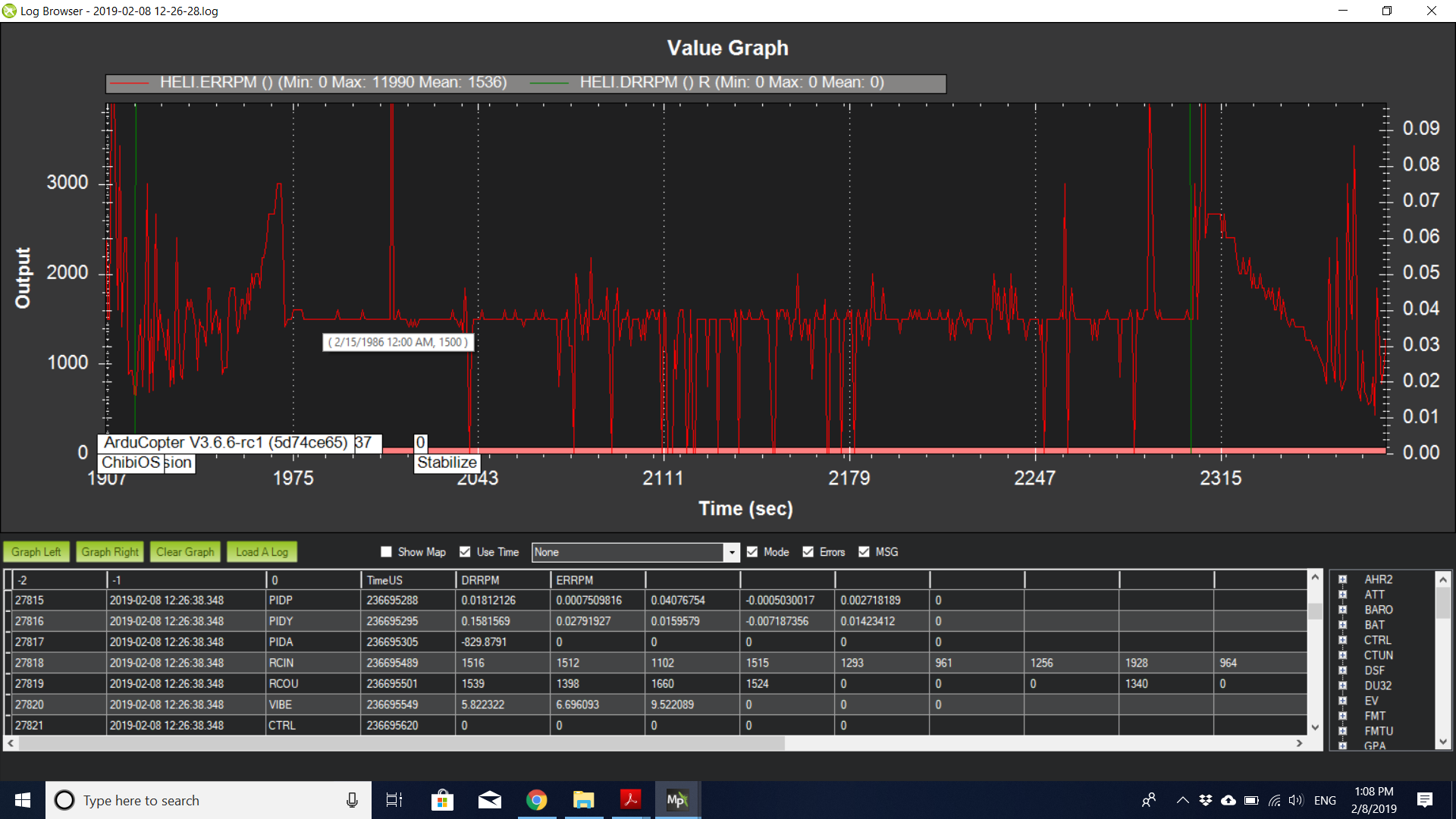
So I wrote a little function that looks for peaks in the y accel data. I just did a short flight and here is a plot of the estimated RPM
I had my ESC set for 1500 RPM and for the most part, it nailed it. As a first cut, I thought it did pretty well. I thought it was interesting how it caught the 2/rev for the spool up and spool down. I peformed some maneuvering and it tends to not do as well. I will have to look at some of the data to see if I can get it to work better, but I think this looks promising as a way to determine the state of the rotor system. Again this is not intended for actively controlling the rotor system.
@bnsgeyer it seems to me some time back you did look at a log or two of one of my bigger helicopters and it did exhibit the same characteristic. I’m pretty sure they all do. With newer controllers with built-in vibration damping this may be easier to detect. On the Pixhawk Cube forum I have seen Philip recommending in some cases to hard-mount the controller as soft mounts don’t tell you what the frame is doing and you’re losing data from your accels.
I have been flying CUAV controllers with built-in damping the same way - hard mounted - and have gotten excellent results from it.
Earlier controllers where folks have gone to great extent to isolate the sensors from vibration, and the controller is more sensitive to it, this may not work as well. So I think it will be an interesting research project.
The binaries have been updated in the 3.6 Governor code to reflect a change I made to add a method of scheduling the gas generator in two-stage turbine engines. The link is in the first post in this thread.
It is a relatively minor change, but it does effectively double the available governor output in the normal operational range to schedule the gas generator to meet N2 torque demand. This will change how the governor droop response setting is applied for piston engines. I flew it in two different piston machines, and both used a 55% governor droop setting after re-tuning.
I flew with a MW54 and 88% droop response worked nicely with the turbine.
The code is latest Copter 3.6.6 with the governor feature added to it. This feature is also now in PR for Copter 3.7 beta.
It depends on the engine and throttle linkage geometry. I have a 23-35-47-61-100 in a helicopter with a 310 engine. Same model of helicopter with a 290 engine I use 18-25-37-60-100
Hi Chris! Been working with Frank on installing this system onto one of our birds. We’re using a Stator Gator sensor, sending the signal from the engine for RPM control.
But this article is stating that he should be measuring ROTOR RPM. Can you clarify?
Hi Chris,
Yes, it is a rotor speed governor, not engine speed. But assuming you can get the Stator Gator signal into the controller’s RPM input and read it, the governor will work using engine speed. But you’ll have to use this code -> if Frank wants to build himself.
That has the latest changes that allow setting the governor range. So, say for instance, you are running 1,200 rpm headspeed you would want to the governor to come in (usually) at 90% N2, so the range would be set to 120 rpm so the governor comes on at 1,080 rpm.
If you’re measuring engine speed with a 7:1 gear ratio, then governed speed with the same headspeed would be 8,400 rpm. Now, for the same range of rotor speed regulation you need 10% of 8,400, which is 840. So the range would have to be set 840 to get the same result for governor engage.
So the code in the above link has this latest change that lets you set the range, the previous build didn’t have that, so wouldn’t work when measuring engine rpm instead of rotor rpm.
Frank is flying either a Navio or Navio2, can’t remember which he said when I talked to him on the phone. So I just added builds for both those boards on the build page to save him having to build it himself. You can get them here ->
Let me know if you get the Stator Gator signal to work with the rpm input on the controller. I’ve never tried that before, but it’s the same as a hall effect so it should work.
It’s certainly possible, but not practical. The GV-1 was never designed for UAV use. This is a N2 governor planned to be integrated with autorotation features. ERPM tells us nothing about monitoring the system to detect drivetrain failure and managing collective to maintain RRPM in autorotation.
Yes. The two functions, governor and rpm, are separate in the code. The governor will use whatever values come from the RPM feature.
The normal use of the scaling would be, for instance, where you have 2 magnets on your rotating component. If that component is turning at 1,000 rpm, it will show 2,000 rpm because it’s measuring 2 pulses/rev. So set the scaling to 0.5 to get the real rpm value.
If you want to read or display relative rotor rpm instead of engine rpm, yes. But in reality it’s just as easy to put the magnet and sensor on the part you want to measure. These little $11 hall effect sensors work fine and don’t require tying anything into the magneto primary like a stator gator does.