Ive bitten off quite a bit. Im using a SpektreWorks carrier board and Im completely lost on where everything plugs in at. Other than their website only covering some differences on the board there isnt any reasonable documentation for newbies. Ive spent way too much time on this steep learning curve. Ive watched youtube and lots of net searching. Most nearly all found is about building other products.
Nice looking board. I took a look at there website and there manual is not very good.
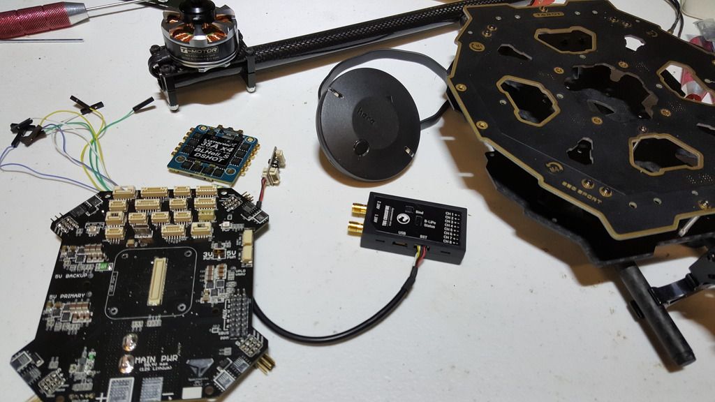
I assume that each corner is the outputs to the ESC’s with the addition of adding Nav lights.
So on top is the AUX pins which you may not need. Each corner is Main1 through Main 8. These are the ESC outputs starting with motor 1 through motor 8. All set for your Hex copter.
Guys I am quite a rookie and figured out the spektreworks board
you can do it
all the ports are labeled in white ink stencil on the board
what I did was take a real good picture of that and keep it handy as I read the arducopter docs
I even hooked a companion computer up to it.
Basically from a documentation stand point it is just like a standard carrier board with ports in different places.
I have mine set up on an octoquad, so if you have questions shout.
I have a 4-in-1 ESC. is there one place on your board that I can pull the signal from instead having to go to each corner? And where would be a single power pull for the ESC? Can I pull power for the ESC from just one the the pads at the four corners? Whats its max amp rate?
You can remap the ESC outputs to any servo pin using the SERVOX_FUNCTION parameters. If you would like, you can remap them to the AUX pins on the front of the board. To set up the output you would like on AUX one, use SERVO9_FUNCTION, for AUX2 use SERVO10_FUNCTION, etc.
What is the max continuous current you expect to draw from the motors? We have tested the board extensively with continuous currents up to 40 amps per pad. If you use one of the sets of pads closer to the main battery input you should be fine with even higher continuous currents.
It looks like individual pins for the ESC connections so I would run the signal cables to each corner for a first time user as mapping the pins could be confusing. So MAIN1 is motor1 and MAIN2 is motor2 and so on…
From the TBS Crossfire, will the BST cable connect to the I2C or the TLM plug on your board? and where can I get a cable to adapt or where can I get a plug for your board to make my own?