Gyropter/Monocopter support with the help of a fourier based Transform

The actual codes used to control, stabilize, and calculate the correct attitude of the drones all use kalman filters.

The drawbacks of kalman filters is that they get dizzy very rapidly when the IMU is mounted on a rotating frame. After a few turns, the algorithm diverges, see video : https://www.youtube.com/watch?v=s3XAoyv0hcc

The idea of the current approach presented here is to add a first harmonic Fourier transform in order to unspin the information retrieved from the IMU sensor.

Here below you will find two views of a rotating airframe exposed to gravity g and rotating at
rad/s. The IMU reference frame x,y,z axis are represented as well

so we have an acceleration vector equal to


Thus, if we apply the Fourier transform to the first harmonic then we find the amplitude A


With the help of Fourier Phase calculation we can determine the dephasing angle

if we chose our aircraft heading to be precisely then we can simply feed the kalman filter with the following accelerometer instant values


(instant value unchanged or averaged over a rotation period)

accelerometer offset won’t have any incidence on the calculation as the resulting dc component will be filtered by the Fourier transform.

Given the heading chosen unspinned instant gyroscope values will be


(unchanged value)

as with accelerometer, the gyroscope offset won’t have any bias incidence on the calculation.

5 Likes

in many branches of science, and engineering and application too, on handles such situations by transforming into the rotating frame. A very familiar case in engineering would be FOC. Wouldn’t it be reasonable to do that here too, and do all filtering, Kalman, control etc in the rotating frame?
(it’s different from your approach because you need a “filter of some length” to get phi_0, i.e., work in the frequency and not the time domain)
just as food for thought
:slight_smile:

Thanks for your input, what is FOC?

field oriented control
I think it could actually be a good guide to what you need
have fun
:slight_smile:

FOC is what will be used to control each motor in the rotating frame, but it is not usable as is to
determine the attitude of the frame.
To calculate the attitude from a rotating frame with noisy sensors we can not avoid using filter of some length, kalman or fourier, digital Filter or others.
But since the motion is periodic, I think Fourier is the most appropriate.

We could simply try to constantly change the frame reference by rotating it in the opposite direction of the main rotation but we will have 3 problems :

  • we won’t be able to determine phi_0
  • the accelerometer values become very noisy when turning in a rotating frame and thus may corrupt the kalman fllter result if used as is
  • accelerometer/gyroscope offsets/bias would have to be seriously taken into account and constantly recalculated/corrected if we don’t want our algorithm to diverge very rapidly.

I have not said that you could copy over FOC one-to-one, I said it uses a concept which you might want to consider
your objections are not valid to that concept, see FOC as an explicit example
anyway, I just thought I share the starting point I would chose, for the reasons it is chosen with much success in so many other areas
have fun
:slight_smile:

interesting. Could you say a little bit more of how you intend to apply it to our rotating frame problem?

I’d like to say that it wasn’t my intention to present a fully fletched-out solution, I just wanted to point you to a well known concept which appears to be perfectly made for your case and which is used in many areas with much success. That’s all. You obviously are not familiar with the concept, so some additional words, but I consider the rest your job :slight_smile:

The basic idea of using a rotating frame is, in physical language, to separate fast time variations from slow time variations (there are of course many applications of rotating frames, but that’s a very common one, and the one relevant here, hence a bit of simplifying here). It’s actually a very simple concept and widely used in all sorts of incarnations, and in your case it just means that your blades are rotating fast as compared to the other variations, such as e.g. to yaw, or to pitch, etc… That is, the basic condition of a fast rotation and a slower variation in this rotation is met in your case, and hence using rotating frames appears as a natural candidate.
Since it’s just a transformation you are not losing (or gaining) any information, which invalidates your 1st objection. Of course you would get phi_0, as you do get all other available info (I predict that you actually will find that you won’t need phi_0 explicitely anymore, since it’s all in w(t).)(again, FOC is a perfect, practical, simple example)
Since the variation of the rotation frequency is slow as compared to the rotation, transforming data into the rotating frame does not add noise (except of the noise due to doing numerical calculations, which is obviously unavoidable whenever you do numerical calculation, and is handable), which invalidates your 2nd objection.
Since all Kalman filtering and control would be done on the slow-varying variations, everything would get much more stable, which invalidates your 3rd objection.(again, FOC is a perfect simple example)

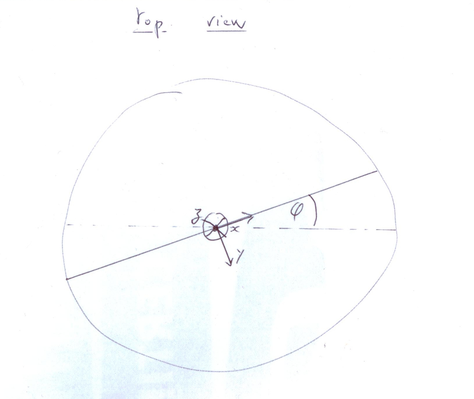
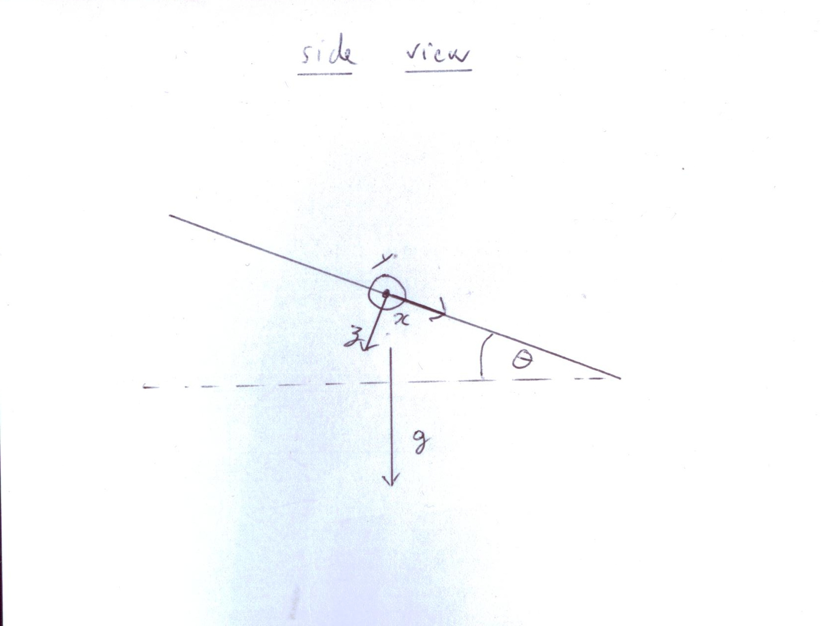
Since your system lives in 3D and not in 2D as for e.g. in FOC, there would be several options to chose the axis of rotation of the rotating frame, e.g. it could be chosen to be fixed in earth coordinates, or to align with the (estimated) axis of your blades. A priory it would not be obvious to me which choice would be better, so this would have to be analysed. The first suggestion would correpond to your choice, and the rotated variables would be simply
vx’ = cos(wt) vx + sin(wt) vy
vy’ = -sin(wt) vx + cos(wt) vy
vz’ = vz
where w would be slowly time varying, w = w(t), and v would be any vector variable (a,v,x,…). You might note the substantial generalization as compared to your Ansatz. But as said, other choices for the axis might be somewhat better. The Kalman and control would be done on the transformed variable v’, which you may note is a slowly time-varying function v’(t). The rotation frequency itself you could get e.g. using an observer, very similar to what is done in encoder-less FOC (I assume it’s obvious that an observer is a more profound concept for estimating w than e.g. a Fourier transform).

As simple as that. Any introductory text on FOC will explain you the advantages of working with the slowly-varying variables. Looking into e.g. NMR would give deeper insights, since it makes more profound use of that concept, but since you need an engineering solution that’s probably not what you want to do.

As said, the rest is your job. Have fun.
:slight_smile:

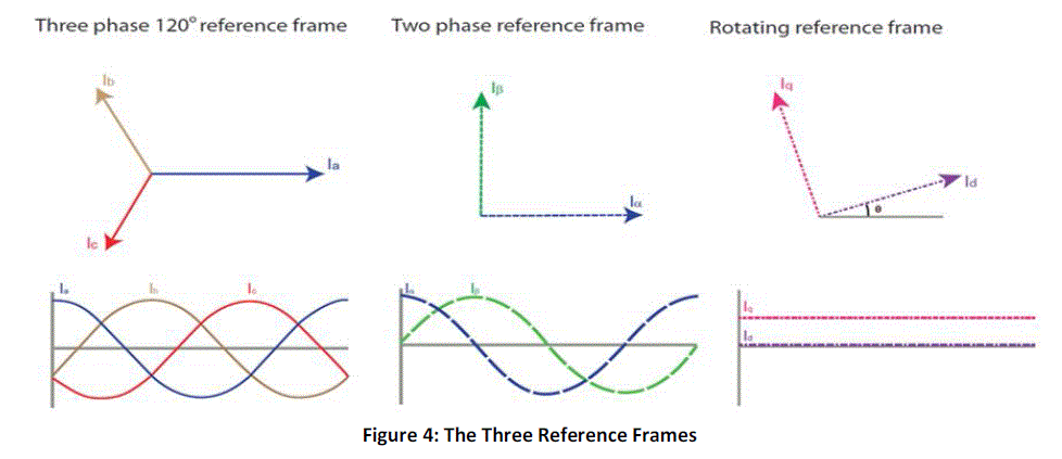
EDIT: going through my folders to find a suitable FOC reference, I actually realized that most introductory texts on FOC do not emphasize the concept well. That’s a bit basic reference which however nicely explains it in simple words: http://www.copleycontrols.com/Motion/pdf/Field-Oriented-Control.pdf, see the paragraph “The important architectural difference…” on the last page. A kind of iconic picture would be this http://www.rroij.com/articles-images/IJAREEIE-1208-g004.gif, there the step from the 2nd to th 3rd plot is the relevant part. Figure 4 in here https://www.nxp.com/docs/en/reference-manual/DRM148.pdf is probably much nicer, this ref might be my favorite on FOC. A bit more physics-related ref would be wikipedia’s article https://en.wikipedia.org/wiki/Rotating_reference_frame, the animation on MR is kind of nice. This too would be a basic intro: http://www.physics-in-a-nutshell.com/article/29/rotating-frame-of-reference, this http://www.maths.manchester.ac.uk/~jm/wiki/uploads/Mechanics/5RotatingFrames.pdf or this http://www.damtp.cam.ac.uk/user/stcs/courses/dynamics/lecturenotes/section4.pdf would be a bit more extensive, all unfortunately a bit too focused on fictious forces, NMR literature would thus be better. All retrieved in few minutes using google :).

1 Like

great post!
hope you don’t mind, I moved the image to the top of the blog post to make it look better when it appears on ardupilotorg.

Thanks for your long thorough explanation, but I don’t agree at all.

What you mentioned is all related to frame reference change. The FOC has nothing to do with our problem.

When not rotating, the heading is determined by the direction pointed by the nose of your aircraft. When it is rotating where is your heading? it is gone
You may argue that we don’t care anymore but actually we do, that’s why I tried so hard to find this phi_0, otherwise what heading will you indicate to the pilot? So my first objection is still valid

concerning the noise, better an image from real life log than hundred of lines of text.

This is the noise of accelerometer in absence of rotation.

The noise for the same accelerometer (in the same test) in rotation


You can clearly see that when rotating, noise from the second, third, or more order harmonic are added to the signal. Such noise are clearly periodical noises and are thus easily filtered with Fourier and not easily by Kalman.

Lastly accelerometer/gyroscope offset are easily filtered by the Fourier transform as they are DC component, but not easily filtered by Kalman.

Your reference frame change proposal is still the only solution for controlling the motors but definitly not a good proposal to address the kalman filtering divergence problem.

If for you, applying the FOC is so simple why don’t you make a test, publish your results here and we will compare your results with the Fourier ones.

clearly you don’t get the concept
but not my problem
have fun
:slight_smile:

@anemos I like your idea to “unspin” the attitude measurement going into the EKF.

For the DCM as used in MatrixPilot, Bill Premerlani used a technique which involved adjusting the yaw feedback when omega was above 50 deg/sec: https://github.com/kd0aij/MatrixPilot/blob/MatrixPilotMulti/libDCM/rmat.c#L745
This resulted in good performance for multirotors.

This was a long time (and 2 codebases) ago, but it would be fun to finally get back into spinning: https://youtu.be/PbgoUnAjBmg

I also found it necessary to “phase advance” the tilt correction to compensate for lag in motor response when spinning rapidly:
https://github.com/kd0aij/MatrixPilot/blob/MatrixPilotMulti/MPMvirtualPose.X/motorCntrl.c#L744
Otherwise the tilt corrections are applied too late (hence on the wrong axis), and a wobble develops.

Really cool, thanks for your input

I like your idea of phase advance, it’s really fun, let’s see if I can implement it in Ardupilot

I tried to feed the kalman filter with unspinned values but that’s a mess. I personally find the kalman filter approach in ardupilot awfully too complicated. When spinning, the aircraft is more stable by nature than a conventional copter and thus with the conjonction of fourier transform should be able to fly very precisally without any kalman filter.
A more simple complementary filter or adaptative filtering would be more appropriate.

Spin stabilization would be very interesting; need to deal with gyroscopic effects at high spin rates.
Begins to look more like cyclic pitch control for a helicopter main rotor, I think.

Hi all,

I have done a PR for monocopter support.

It works well in SITL.

The next step it to build a real one! I hope to have something flying in the next week or two.

1 Like

Hi, any update on this ?

I am considering building a Samara / Gyro / Monocopter

Very impressive work BTW

1 Like

No updates I’m afraid.

I made an attempt at building a real one to try but didn’t have much luck at getting the dynamic stability that should be possible before applying the control system. The code is there ready to try, happy to do firmware builds and try and work out bugs, if you have a go at building one.

Has been on my list of projects to re-visit, but as ever there are too many things and not enough time.

1 Like


Hi, some 5 month ago I built a very simple Samara “demonstrator”.

The idea was to understand the dynamic and balance of such a model.
After some refinements I managed to get it flying in a stable manner.
I could manually control the throttle and a flap situated at the trailing edge.

What I retained from these trials :

  • The longitudinal axis (pitch) works pretty much like a flying wing.
  • The CoG has to be situated in the same proportion than it would be in a traditional flying wing.
  • The flap works like it would in a flying wing, when deflected upward (trailing edge of the flap up) the pitch angle and the lift increase. Opposite is true.
  • Stability was achieved easily in my case. At lower RPM the wing would fly in a cone shape until the drag was too high to maintain flight. At higher RPM the cone angle was more flat but the Samara behaved “well”, like a gyroscope.

Since I wanted my model to be able to take off from the ground I installed a wheel, several reinforcements and an aluminum arm.
Sometimes the take offs were brutal for the propeller and the wing itself as it bounced on the ground at full rotational speed.
The general aerodynamic is very bad and the power requirement for sustained flight was high considering the size and mass of the wing.

My idea was to make a kind of POV display with high speed RGB leds as it has already been done previously.
Maybe a project for the next winter …

Edit : Flights were ~5 not 6 month ago

1 Like