Recently I tried to control my oil engine using the APM flight control internal governor, but I found a difference from the commercial flight control control i’ve used before. Through the commercial flight control used before, my understanding of the speed governor is that when the engine starts, the throttle pushes to the set value, the engine will turn at the fixed speed value, no longer because of the upward push throttle speed changes, but by adjusting the internal speed governor found that this is not the case, I found that the throttle pushed to the set value, Pushing the throttle up will still go up. I used a motor to build a test platform for testing. The tests are as follows: First configure H_RSC_GOV_SETPNT=900 H_RSC_GOV_RANGE=100 H_RSC_GOV_DISGAG=10 H_RSC_GOV_TCGAIN=85 H_RSC_GOV_DROOP=100 Then configure the throttle curve, when no GOV is configured to test the throttle at about 50%, the speed is 930 RPM, so I configure the throttle curve as follows: H_RSC_THRCRV_0,15 H_RSC_THRCRV_25,30 H_RSC_THRCRV_50,50 H_RSC_THRCRV_75,60 H_RSC_THRCRV_100,60 After the configuration, in the throttle push process found that the motor is not set at 900RPM as imagined, according to my understanding of APM governor if motor speed in the 900±100 range, the motor speed should be automatically adjusted at 900RPM, in the test process I slowly push the throttle, It is found that the motor speed will vary depending on the throttle adjustment. It is not that the throttle is pushed to a certain value after the fixed speed at 900rpm. And in my test, when I set the motor speed to 930RPM, the hand blocking the motor rotation can find that the output value of the ch8_out will change greatly, which indicates that THE GOVERNOR is also at work, but the motor speed is not set at 900RPM.
Is there something wrong with my test. Why the speed didn’t last at 900 RPM?
@ ChrisOlsonCan you help me resolve this problem, thanks.
Perhaps this post will help:
The governor in Copter 4.0 was designed for piston engines and turbine engines without a governor like the Turbine Solutions 44i. Its purpose is to provide automatic adjustment to the throttle curve to prevent having to retune all the time due to change in density altitude.
Some people have successfully used it with electric, even though it was not designed for that. Electric was back-burner priority since most ESC’s have built-in governor. And if they don’t, electric flies quite well on just throttle curve since there is no change in power output of an electric motor with change in air density and humidity.
Thank you ChrisOlson. My goal is to use it on a rotor engine. The motor is only used for testing. I tested and found that if I throttle the motor until it reaches the specified speed, I can prevent the motor from turning by hand, and I can see that the throttle output changes. When I increase the throttle and increase the speed, when I stop the motor from turning by hand, I find that the adjustment will only be performed after the speed is less than H_RSC_GOV_SETPNT. For example: I set H_RSC_GOV_SETPNT = 900. I pushed the throttle. When the speed reached 900 RPM, I blocked the motor to generate friction to reduce the speed. I found that the governor would adjust it immediately. If I continue to push the throttle to adjust the speed to 950RPM, I once again block the motor to generate friction to reduce the speed. During the speed of 900RPM-950RPM, the governor does not adjust the output. Only after the speed is less than 900RPM will the output be adjusted. . Therefore, through this test, I found that the governor does not adjust until the RPM is less than the H_RSC_GOV_SETPNT value. But for a rotor engine, if you want to maintain a constant speed, it means that during the throttle adjustment process, if the speed is greater than H_RSC_GOV_SETPNT, the speed is also unstable. Then the role of governor is more like preventing the engine speed from decreasing to H_RSC_GOV_SETPNT instead of keeping the speed at the H_RSC_GOV_SETPNT value.
I read your other article, which mentioned that the throttle curve needs to be adjusted. According to my test, the understanding of this governor is that if I want to set the speed at 900rpm, I should first push the throttle record without the governor. When the speed reaches 900rpm, the throttle value, for example, is 40%. Then configure the H_RSC_THRCRV value as follows:
H_RSC_THRCRV_0: 10
H_RSC_THRCRV_25: 40
H_RSC_THRCRV_25: 40
H_RSC_THRCRV_25: 40
H_RSC_THRCRV_25: 40
So no matter how I push the throttle, the speed should always be 900rpm.
But this should be different from the original intention of this governor. For example, at 0 meters above sea level, the throttle that reaches 900 RPM is 40%, but at 2000 meters above sea level, the throttle value should be greater than 40%. Then you need to readjust the H_RSC_THRCRV value.
The helicopter must be set up and adjust the throttle curve so it flies under all load conditions with the throttle curve alone. Then the governor can be turned on, adjusted and set so it makes the adjustment to the throttle curve for changing density altitude conditions.
It is impossible to test, or determine anything, on the bench with an electric motor. The torque characteristics of electric motor vs combustion engine are not the same.
Electric motors produce peak torque, but zero shaft power output, at zero rpm (stalled). And peak efficiency at about 50% rated amp load. Piston engines produce peak torque and reach peak efficiency at max BMEP, which occurs at wide open throttle at a point below the peak of the horsepower curve. Turbine engines are similar except peak efficiency is reached at maximum shaft horsepower or thrust.
I would suggest following the outline to set it up in a real piston or turbine helicopter. It will work just fine, as it was designed. It has been flown 100’s of hours. It might be new in Copter 4.0, but it is not a new un-tested “feature” otherwise, flown for just about year in commercial applications before it ever appeared in Copter 4.0.
This will be hard for people to understand but you have to look at the power curve of a normally aspirated piston aircraft engine to get a better grasp on the concept of throttle vs power.
At takeoff at sea level you will use maximum power - 28.5" of manifold pressure. As soon as you have positive rate you will pull the gear in, retract the flaps and clean the airplane up for climb. Power is reduced to 25 square, 90% of sea level power, to keep the engine within its temperature limits.
As you climb, to maintain 90% power you have to open the throttle until it is wide open at around 6,000 MSL. If you cruise altitude is 10,000 MSL you will be down to around 20" of manifold pressure with the throttle wide open and reduce rpm with the prop governor to peak torque. This is where the engine has best efficiency. Throttle wide open (peak volumetric efficiency), rpm at peak torque. This yields best specific fuel consumption (lb/hp-hr).
The governor that is now in Copter 4.0 was designed with this in mind. You tune the throttle curve (the baseline) for a specific density altitude, say a dryer cooler day. Now you get a change in density altitude - warmer more humid day. The thrust efficiency of the rotor, and the power of the engine both drop. The difference in thrust efficiency of the rotor is not enough to get the throttle curve to compensate. So you need a system that can maintain that 25" of manifold pressure by opening the throttle further. This is what the governor does - automatically.
So I hope you can see that analyzing what the governor does with an electric motor is totally pointless. It was not designed with that in mind.
Thank you for your kind help. I will try and adjust again.
@ChrisOlson
hi ChrisOlson,Through the internal governor, my engine speed was fixed, but it didn’t feel perfect.
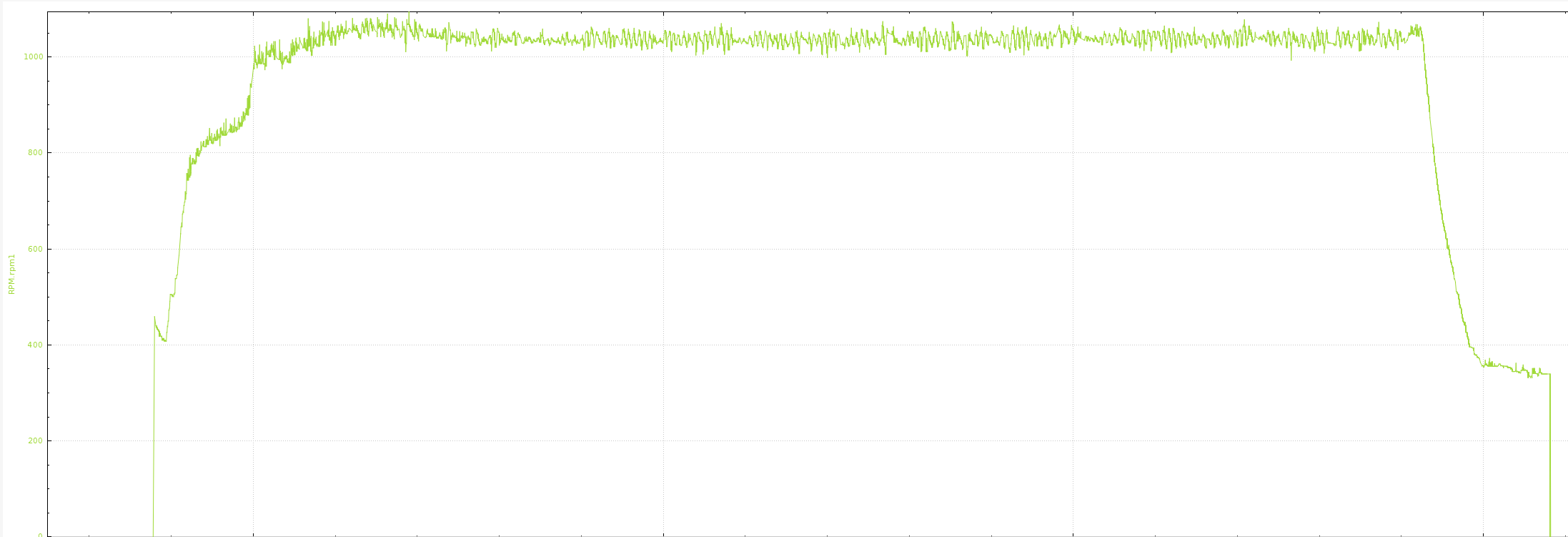
The curve above is the effect of my rotor’s constant speed.My speed setting is about 1060RPM. I found from the curve data that the maximum speed is about 1080RPM and the minimum speed is about 1000RPM.So the change in my engine is about 500RPM. So it feels that the engine is very unstable.My related parameter settings are as follows.

Throttle settings are as follows.My method is to set a throttle to let the drone reach a fixed speed on the ground.

During the test, I tried to modify H_RSC_GOV_DROOP and H_RSC_GOV_TCGAIN and found no improvement.In view of the unstable speed of my engine, can you give me some adjustment suggestions, thank you
This is your problem. The governor in ArduPilot is an adjustment to the throttle curve to compensate for differences in density altitude. It requires the throttle curve to be tuned properly so the helicopter will fly normally on the throttle curve before using the governor.
If the speed sensor were to fail your throttle would be locked at 19% power. The helicopter would likely crash if the sensor failed.
thanks,i misunderstand it,i will try tomorrow.Hope to achieve good results.
Also posted this in the original description, then found this discussion.
I’m setting up an electric 700 class heli with a Pixhawk 1 (2.4.8), running Arducopter Heli v 4.07 (tried also beta 4.10) and a Hall sensor for governor control. I’ve set the RSC_MODE = 4 and I have ported out (board def) Aux 5 and 6 for GPIO sensor input.
BUT I’m utterly unable to find the parameter RPM_PIN to set up for “55” (aux input 6).
Am I using a wrong version, do I need several reboots, or did I miss something? thx!
Please post your parameter file so I can check your setup. Thanks!
Bill, thanks. File attached. Yesterday I shifted the governor mode to “3” (throttle curve) to work a bit more on the frame, but I just changed it back to “4” before downloading the parameter file. I can’t remember changing anything else yesterday.
The Hall module doesn’t flash it’s output LED, indicating that the GPIO pin is still an active output forcing the module output down. As expected.
700heli_21july.param (15.4 KB)
@mike_o If you aren’t seeing the RPM parameters in your parameter list, it is likely that the board doesn’t support RPM measurement for one reason or another. My only guess is that the code has grown too big and in order to keep it to a size that could fit on this board, they trimmed everything that was not necessary. @rmackay9 or @tridge could you shed any more light on this issue.
Sorry. I’m sure that wasn’t the answer you were looking for (i.e. buy a new board).
Bill, haha, yes, not the answer I was hoping for, but it’s possible explanation I hadn’t thought of at all, thanks. Let’s see if one of the two gentlemen chimes in 