Hello, not sure I picked the correct category for this post.
I am building a drone from scratch. I am using H743-WLITE.
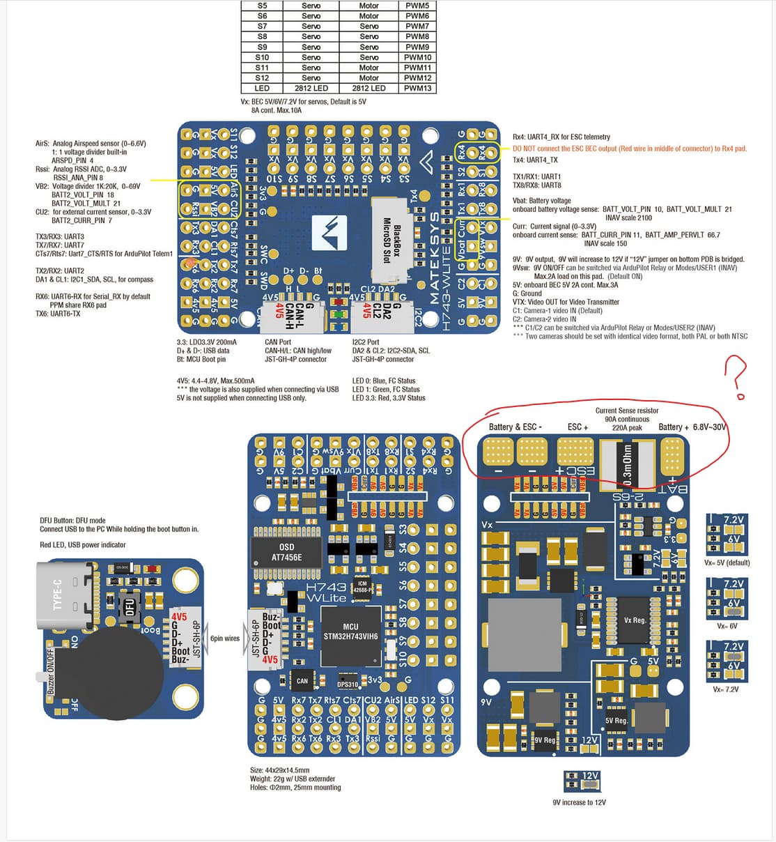
I don’t quite understand what the ESC pins are for on this FC?
Do the ESCs get powered directly from the FC? Because my understanding was that the ESCs power supply is coming directly from the battery. Say from a board connected to the battery, with enough terminals for all ESCs.
Can someone please help me clear out the confusion?
Normally you are right and ESCs get connected directly to the battery. However on this flight controller you have a built-in PDB / BEC with voltage- and current measurement. So yes, if you don’t continously exceed 90A you are supposed to connect the battery and the ESCs to the WLITE and route the ESC supply current through the FC.
I’ve seen you wrote in a different post that you are building a heavy-lift Y6, you probably want to connect the ESCs directly to the battery, but do the calculation on expected current. Depending on the rest of your setup (like voltage, kv, prop size) you may exceed 90A easily with an up-to-30lbs vehicle.
If you connect the ESCs directly to the battery you need to get current measurements from somewhere else (probably your ESCs).
Ok that sounds clear enough to me. Thanks for that.
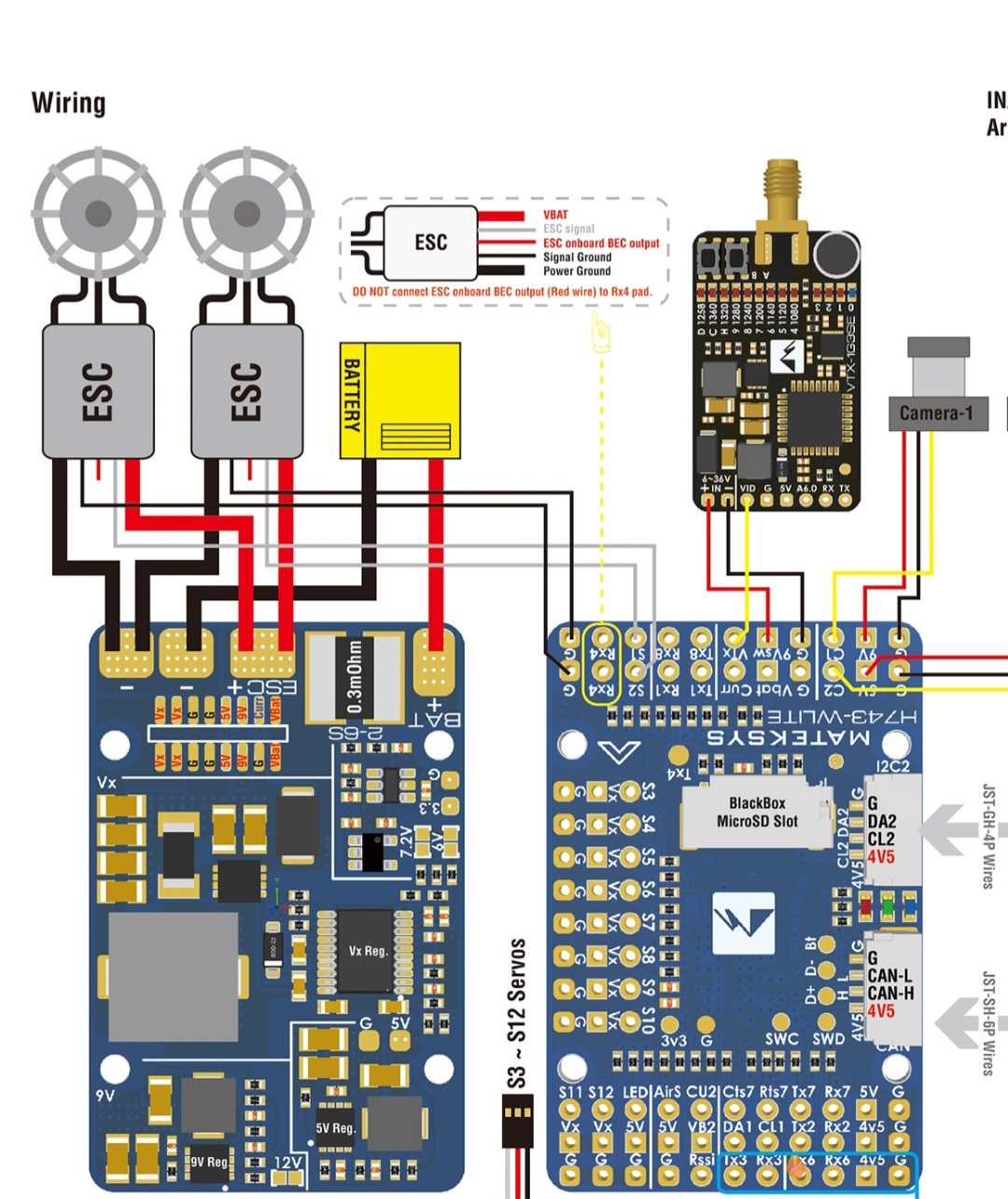
Now here’s another thing I am unsure about. The wiring diagram below shows only 2 ESCs while in my case I will have a total of 6.
First off, I assume I would need a separate BDB to solder all the ESC power wires to since I would run out of physical space on the FC.
Second, again the current diagram shows an example of 2 ESCs and each with a signal wire of it’s own. Where do I connect the signal wires of the other 4 ESCs?
It looks like you lack the basic knowledge. Perhaps it would be better if you built a small quad copter first before investing a lot of money and other things in a heavy-lift Y6 …
It probably shows only two ESCs and motors because this FC is specialized for planes and most planes have two motors or less. That doesn’t mean it isn’t suitable for multirotors though, just so you know why it only shows two.
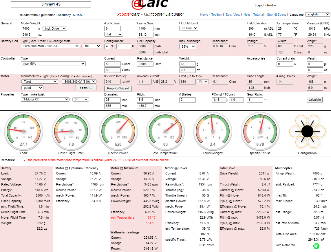
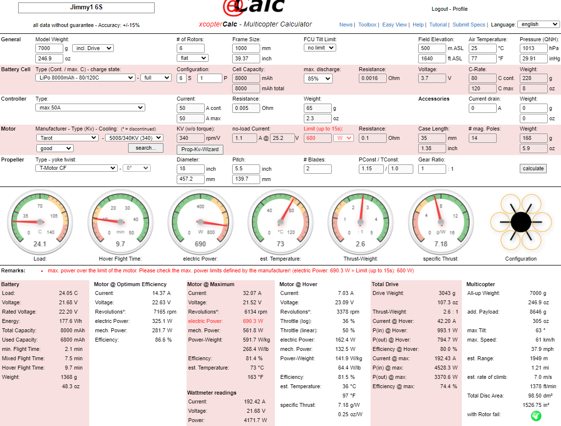
Did you do the calculation how much current you will draw during normal operation? That determines how you have to connect the ESCs. If you don’t know how to calculate this, I recommend to buy a subscription to eCalc and to put in your parameters there. It is not expensive (10$/year) and it is a great helper in design questions regarding the propulsion system.
If you did the calculation already, do you expect more or less than 90A?
With 6 motors you will definitely need a PDB, the question is if it has to be smart (with voltage and current measurement) or if it can be dumb (just a splitter without measurements).
If you expect less than 90A:
Battery → FC → dumb PDB → ESCs
If you expect more than 90A:
Battery → smart PDB → ESCs (power)
Smart PDB → FC (signal wires for voltage and current measurement)
The signal lines if the other 4 ESCs go to S3 - S6, like Reinhard said.
OK got it. Makes sense. Thank you!
I do lack basic knowledge, but the frame, ESCs, Motors, and Blades have already been provided to me. My investment is minimal.
Look at the example for the H743-Slim.
The function connections are the same but you don’t have an 8 pin connector on that FC so you will be breaking out that cable to connect to the S1-S8 pins on the WLITE. Also, you need to connect the “Curr” pin on the PDB to the CU2 pin on the FC and configure the current monitor settings as stated.
Also, if you want ESC serial telemetry (assuming you have ESC’s with that) you need to connect the “Tlm” pin on the PDB to a serial port on the FC.
Nope. It has the voltage regulators on it that powers the flight controller itself. You probably could get away with finding your own source of power for the board but it’s probably the easiest to power the through the PDB that comes with the WLITE and use the CU2 pin for the current readings of the external PDB.
This PDB looks good, 265A is plenty. If you are running on more than 4S you will hit the power limit of the motor (700W) before the current limit of 40A anyway.
I just put it through eCalc with arbitrary (but plausible) values for everything I didn’t know about your drone to find some max values.
This is for 4S:
Max TOW: 7kg
Max prop size: 25"
Configuration here.