In Pixhawk 2.4.8 two STM32 microcontrollers are mounted:
STM32F427VI as a FMU chip on schematic
STM32F103C8T6 as IO chip on schematic.
I have STLINK v2 programmer, but I can’t find where I can download *.hex or *.bin files to IO MCU.
I want to create custom board with the same components, but other shape of PCB. Thats why I’m looking for the same firmware which is in my 2.4.8 board.
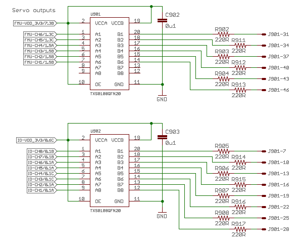
BTW, if you are making a new board, I have always wondered why servo signals have 3.3V levels: connecting the TXB0108’s to some internal 5V supply would solve WS2812 voltage levels incompatibility mentioned here and there.
So not knowing if there is a reason, perhaps some kind of soldering jumper to choose supply to those ic’s would be a good option.
Thank You for Your reply.
I did it before, all of my 5 boards has “Read memory protection” enabled option, so it is unable to read flash. I checked it via STLINKv2. Using JTAG I’ll be able to download flash???
Thats why I’m looking for bin from releases etc.
I’ve read on another topic that firmware into IO MCU is downloaded from FMU MCU during startup but I dont think so it is true, need to check it.
Yes, TXS0108 is TTL voltage converter, if You want to use 5V output signal for ESC,SERVO,s You need to supply VCCB from 5V. Remember VCCA < VCCB always!
There is a significant difference betwenn 2.4.6 which is the last official rev and 2.4.8 which is “upgraded” by china, removed many supply regulators etc.
All I want is to redesign shape of PCB and include my electronic components at the same board. Thats why I need to know how to achieve firmware for STM32F103C8T6
Servos supplied by 5V works perfectly on 3.3V signal. Maybe it is created for next generation servos and ESC to avoid convert its signal inside from 5 to 3.3v. Or maybe it is a bug
Yes - one UART bidirectional
I’ll focus on it, thanks! I really dont know why IO firmware is that hidden and complicated to achieve *.hex file like main FMU MCU
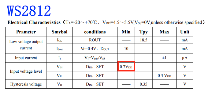
So depending on its supply, input level to WS2812 should be between 3.15V and 3.85V. If the FC output stage (TXB0108 on Pixhawk) is supplied at 3.3V, its output level will be less than that, not enough for WS2812.
When the Pixhawk was designed, possibly there were no WS2812’s. I don’t know if recent designs have corrected this.