I’m posting this perhaps only for my own benefit, but here’s what I had to do to get Yash’s Python scripts working on a fresh Pi Zero Raspbian Bullseye headless install with the mmWave board connected via OTG cable:
@rishabsingh3003, can you confirm the following parameters are the correct method for setting things up, and that the OBSTACLE messages are supported on Rover 4.1?
I think the only issues so far are all on my end - just getting the correct versions of everything and making sure the Pi is powered with a good enough cable/adapter.
Thank you both for the help so far! I hope to expand on Yash’s work and develop native support, possibly even through the CAN interface.
With the following two code updates, I have Yash’s mmwave_to_mavlink.py script working on a Pi-Zero connected to a Cube Orange.
Line 21: obstacle_distance_msg_hz = 10
Line 100: sched = BackgroundScheduler(timezone='Etc/UTC')
I think 60Hz was a bit too fast for the Pi-Zero. The limit seems to be around 15-20Hz (and may be faster if writing to stdout is disabled, especially if the output stream is tied to network speed over ssh).
The line 100 edit avoids a deprecation warning from APScheduler.
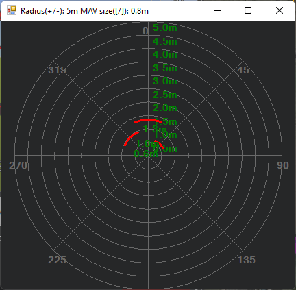
Looking forward to getting outside and testing this in a live environment before proceeding with a native driver (this first test was just on my desk).
@rishabsingh3003, it doesn’t appear that a scan elevation of less than +/- 30° is possible with the radar, and I’m not seeing anything in the Python code that filters messages based on their relative location to the ground or horizon. How does Rover filter obstacle data from ground clutter?
If I understand correctly, the steps to getting this working via direct UART comms will be:
Determine how to save a config to the radar unit such that the user port is not required to be connected at startup (avoiding the use of an additional UART on the autopilot).
Establish comms with the data port via HAL
Parse incoming data and pass it to the PRX controller
Lovely…I could test the drone on table top with Raspi and Jetson Nano. However couldn’t complete outdoor trials. Will be gr8 if you can do that and also update the codes as per field trials. Wish you best…!!!
Can check this too https://beaglebluevoyager.com/
@Yuri_Rage filtering ground clutter is the biggest problem we face in ArduPilot avoidance. When we have a huge FOV, it is possible to employ things like RANSAC or similar algorithms to figure out the ground plane and filter it. But we rarely have the bandwidth to process such huge point clouds inside the flight controller. We, therefore, expect the companion computer/sensor to do it.
Also with normal 1-D rangefinders, it’s impossible to know when it’s detecting the ground and when it’s detecting obstacles.
Last year I did add a feature for Copter ONLY. IF you have a downward-facing rangefinder, an “obstacle” detected near that range is rejected. But that does not work in rover.
Regarding the steps you listed… that sounds about right to me. Let me know if you want to get on a call and discuss the last step about the proximity library. It can get a little confusing for first time
I understand for sure and am happy to have identified some of the potential struggles.
For the moment, I’ve actually run into a major hurdle that is slowing progress to a near halt. The dev board does not expose a UART on any pin header. It is exposed via USB or on the 60 pin connector, but a mating connector/cable has proven difficult or even impossible to source.
The CAN1 port is exposed on a 1.27mm pin header, to which I can easily connect. However, if I read correctly, the factory “demo” flash only communicates via UART, so I would need to develop onboard firmware to even get the CAN port working, and THEN I could explore ArduPilot support.
I was hopeful that this board could be used in a fairly “off the shelf” manner, despite its intent as a dev board, but I’m beginning to think that the companion computer may be a “necessary evil” here.
I’m curious to hear your or Yash’s thoughts on the best path to reasonably support the radar.
Ah that sounds painful. I am not sure about the sensor, as I never had it in hand. I only helped Yash with the mavlink bits of the script, so he will need to reply on the connection issues
I know @tridge spoke a few time about implementing a USB HOST on STM32 I dont know if it can be done on an existing FC like a Cube Orange or if it need a whole new design
I’ve recently delved into ROS a bit and I think perhaps the sophistication of the TI module may best be leveraged by a companion not unlike Yash’s proof of concept. I’ll continue exploring the concept.
In the meantime, I have a 24GHz radar on the way courtesy of @geofrancis with a narrower FOV and simpler serial protocol, so we may well see native mmWave support for ArduPilot soon, even if it’s not via this particular means.
Hi there…that’s where I was stuck. I too wanted something readily integrable but wasn’t the case with this mm wave radar. Only UART was available for out of box demo and hence the reason for going with companion computer. Required some dedicated effort for tweaking the firmware and writing drivers for direct integration with FCU.
How are you getting the vector data from the TI Board to the companion computer? Is this provided with the TI board? I have some ideas on how to make this work and exploring it further if your interested.
Read the rest of the topic and have a look at the code base. It’s pretty obvious how the dev board interacts with the companion computer and autopilot.
@yutri_rage What is the config file you used? What was the range you got for that, and for what kind of obstacles? Also have you tried TI’s AWR 1843, and what are your thoughts on that when compared to 6843? @yashlancers your suggestions will be valuable too
As you have worked with mm wave radar as a proximity sensor and also achieved the obstacle avoidance could you please help me out doing the same?
I read your posts and I have a little confusion so just want to clarify some doubts and need your guidance.