No, its just a convenient way of setting up the throttle notch. You can also use FFT to drive the notch if you want but the setup is a little more complicated
Hello Andy!
Is there any documentation on how to set up the FFT driven notch?
I reckon you mean the
INS_HNTCH_MODE=4
Well, thank you
So, if I understand this correctly, setting the FFT_xxx and the INS_HNTCH_xxx parameters correctly, and keeping the FFT_ENABLE=1 at all times, will do the job?
PS.
my params are:
FFT_ATT_REF,15
FFT_BW_HOVER,46.67492
FFT_ENABLE,1
FFT_FREQ_HOVER,75.0974
FFT_HMNC_FIT,10
FFT_HMNC_PEAK,0
FFT_MAXHZ,200
FFT_MINHZ,20
FFT_NUM_FRAMES,2
FFT_SAMPLE_MODE,0
FFT_SNR_REF,25
FFT_THR_REF,0.04576755
FFT_WINDOW_OLAP,0.75
FFT_WINDOW_SIZE,256
INS_HNTCH_ATT,20
INS_HNTCH_BW,25
INS_HNTCH_ENABLE,1
INS_HNTCH_FM_RAT,1
INS_HNTCH_FREQ,37.5
INS_HNTCH_HMNCS,3
INS_HNTCH_MODE,4
INS_HNTCH_OPTS,16
INS_HNTCH_REF,1
I would suggest you narrow the notch to start with to protect against excessive phase lag at low frequencies. The other parameters look correct.
1 Like
OK, I will do a test, with:
INS_HNTCH_BW,10
How about the INS_HNTCH_FREQ? Should this be my peak frequency, (as seen at the FFT diagram), or I should lower it? My drone is a heavy one with 32’’ props, so it has low frequences
If you are driving the notch with the FFT then it is the ratio of FREQ/BW that is important rather than the absolute numbers. Also make sure the FFT is giving you something sensible before switching it on. FTN1.PkAvg should give you a reasonably clean line in hover
1 Like
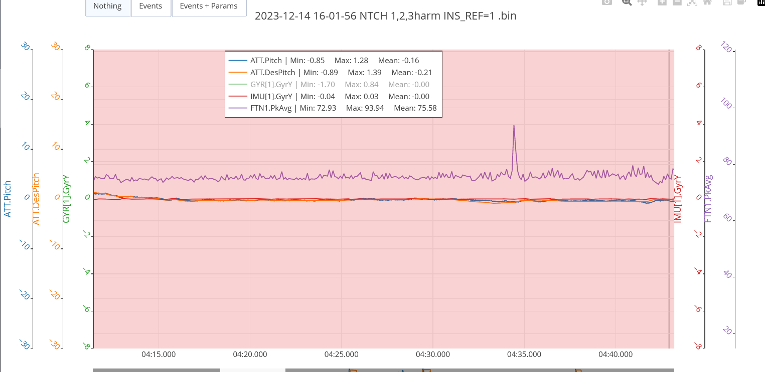
This is the FTN1.PkAvg that I get in hover. And yes I am using INS_HNTCH_MODE,4, driving the notch with the FFT.
So I shoud tweek the INS_HNTCH_FREQ/INS_HNTCH_BW ratio?
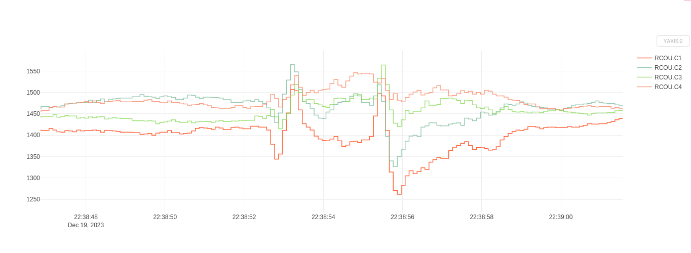
It may have a phase lag problem, because when I enabled the notch filter some oscillations started at hard braking:

log file: https://drive.google.com/drive/folders/1nFwyxskw400kaA6zk5UvB8WJvCoMqrc4?usp=drive_link
You will need to retune with the notch. You should try and make the notch as narrow as possible without the noise getting through.
1 Like
Access denied on that log
1 Like
I’m not sure what you mean by
but it does not sound good.
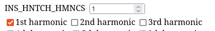
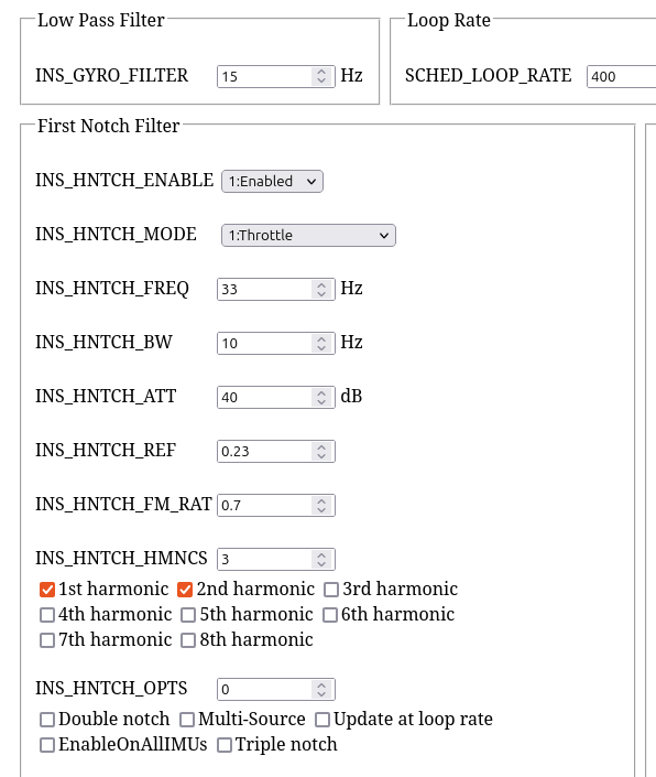
The configuration you have now is OK but you just need 1 harmonic, no more:
My opinion is you dont need to set the notch filter to run on more than one IMU unless you are expecting frequent EKF/IMU changes, such as in some harsh environment.
![]()
Andy might have a reason I couldnt think of, and he definitely knows infinity+1 more than me about this.
I mean both
INS_HNTCH_xxxx
and
INS_HNTC2_xxxx
I guess setting both of them can supress more vibrations, I see that there are some areas that are not harmonic of each other and they are not targeted by the one notch.
About EnableOnALLIMUs, you are right. Andy in his video sets
No, I dont believe you need two separate notches at all - that is only required when you’ve got two totally different noise sources, like a cooling fan or ICE generator, causing a noise frequency unrelated to the motors.
You dont need those other options either - the notch you had was working perfectly, but with unnecessary harmonics.
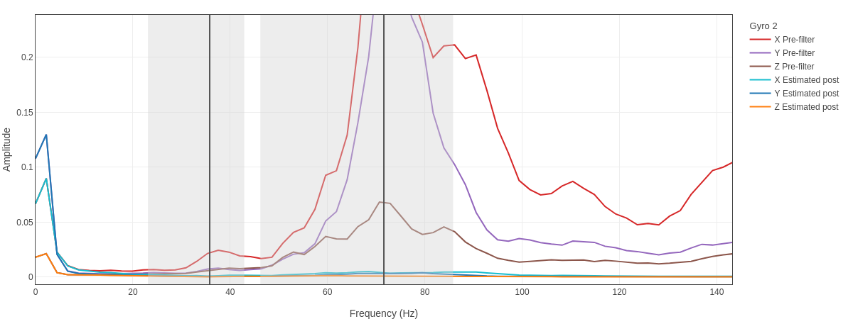
What you had in that flight:
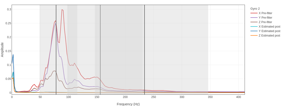
What you will have with a couple less harmonics:

Notice how the post-filter lines along the bottom of the graph are equally flat and noise free in both cases.
You cant take out more noise from that ![]()
Adding more options and harmonics only puts more load on the flight controller, possibly introducing lag in the PIDs manifesting as oscillations and instability.
INS_GYRO_FILTER does a lot of the work, and tries to attenuate noise above this frequency you’ve set. The notch filter is only needed for the worst noise that can get passed the low pass gyro filter. This is why I havent even shown some of your higher frequency noise in these screenshots, because it doesnt get passed the gyro filter.
You could probably even lift your gyro filter setting to 15 and there wouldnt be much issue. Basically the higher you can get this without letting in too much noise - the better the flight controller can tell what’s really happening with the attitude.
1 Like
I did a flight as you suggested, INS_GYRO_FILTER =15, flew well.
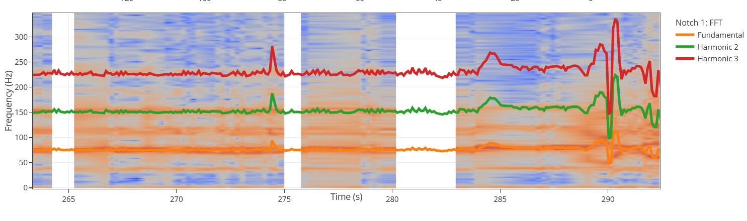
I can see that some IMUs have better signal than others:
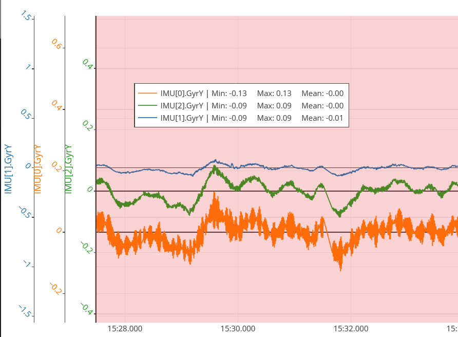
IMU[1].GyrY seems to have less vibrations passing through. Is this normal?
My notch filter settings are:
INS_HNTCH_ATT,20
INS_HNTCH_BW,15
INS_HNTCH_ENABLE,1
INS_HNTCH_FM_RAT,1
INS_HNTCH_FREQ,30 (2:1 FREQ to BW ratio)
INS_HNTCH_HMNCS,3
INS_HNTCH_MODE,4
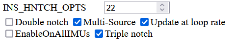
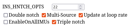
INS_HNTCH_OPTS,22 (as @andyp1per recomends in his video)
INS_HNTCH_REF,1 (I reckon that this needs to be 1 in order for the FFT to drive the notch filter)
I am experiencing some oscillations when braking when I started appliyng the filters:
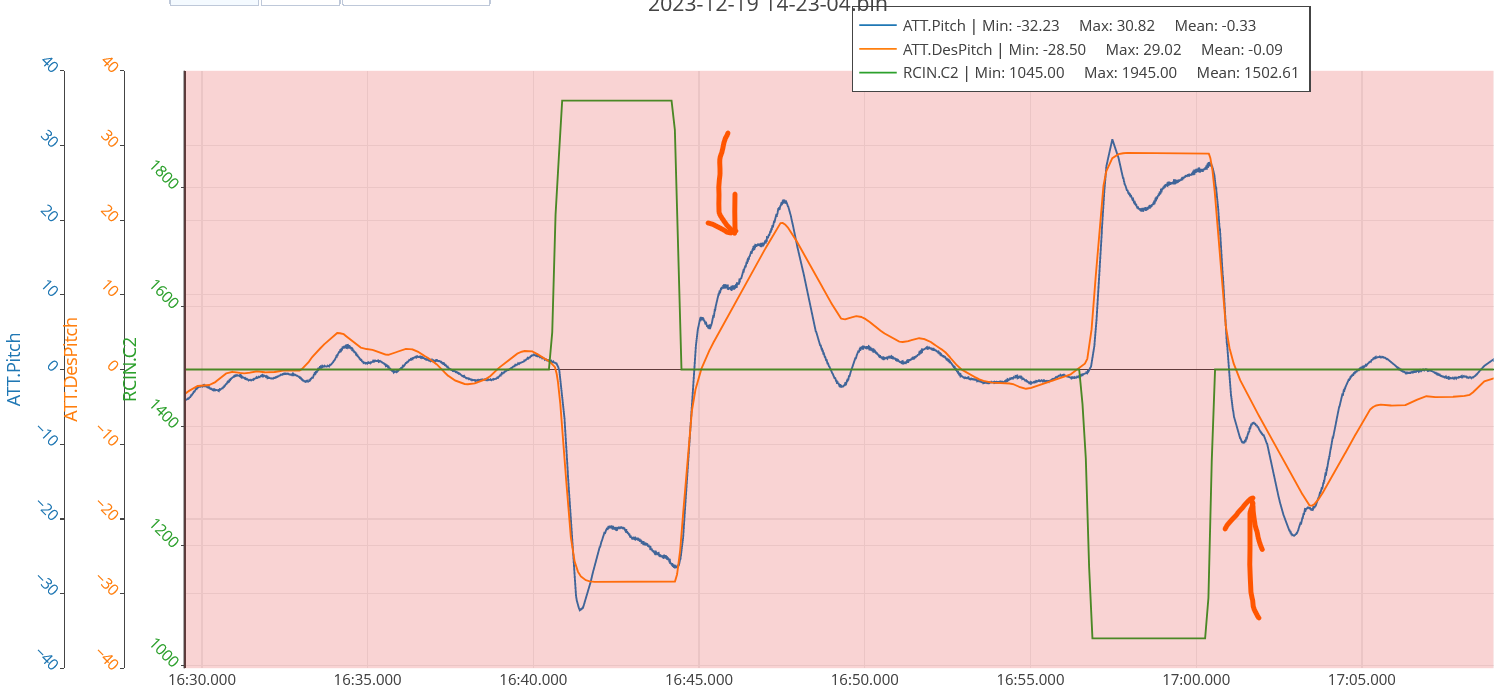
This may be bad PIDs? Or maybe something related to the brake controller?
This is a 35kg octorotor
log: https://drive.google.com/file/d/1m20MNJ-azQtUMknlV_d2pOgNRsbBD8-D/view?usp=drive_link
Triple notch is fine if it suits, but update at loop rate and multi source is doing nothing for you.
They are not needed in relation to using FFT.
- Multisource is usually used with ESC RPM data, and produces a per-motor notch. This is useful for small nimble copters or fast copters where motors can often have vastly different RPM. Even if you had the ESC RPM it is not always necessary to use the per-motor notches, especially with bigger copters.
- The loop rate option is usually used on small nimble copters where motors are likely to change RPM at exceptional rates
Generally the idea is to use FFT to find settings that work, then disable FFT and use throttle-based HNOTCH. This gives reasonable performance with minimum load on the flight controller.
This is what I would be using with your copter:
For this result
One of the key considerations is the size of your copter - the props and motors are not changing speed at any alarming rates. Even when manoeuvring your motor outputs are only changing in the order of a second (not sure I said that correctly). In your log there is about 10 commanded speed changes per second - this is nothing for the flight controller to track with a notch when the differences are rarely more than 50 PWM or 100 PWM at a time, and often less.
And using a throttle-based notch filter isnt going to miss the noise and motor output changes. You can see the throttle doesnt actually change a lot.
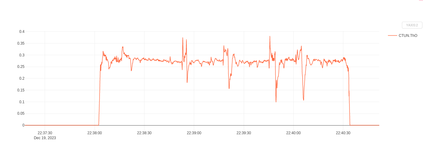
Did you see Andys graph of throttle output in his video?
Departing a long way from the original discussion title:
Anyway - I’m interested in how these big copters are tuned and the result. So what i would do now is set the HNOTCH parameters I pictured above, and disable FFT.
FFT_ENABLE,0
And do another short test flight with some pitch and roll. Try to have AltHold and Loiter in the one flight.
Let’s see that log.
I suspect you will just need an Autotune with the updated notch filter settings.
Actually if you wanted to start your own discussion for your large copter tuning that would be great, and we can leave the FFT-specifics in this discussion.
1 Like
Thanks for all the help, Shawn!
The drone has Cube Orange+ and it reports maximum 40% CPU load. Also, this is a cargo drone that will be having variable load configurations. Do you think Throttle based Notch Filter is still preferable versus the FFT Dynamic?
You are right, we are digressing from the topic.
I will set the filters as you suggested, tune again and then make a seperate thread.
By the way today we did an other autotune before reading your suggestions, here is the log:
Also set this:
LOG_BITMASK,180222
Your log is a bit excessive for no good reason - I mean there is no drastic reason to log so much extra data in your case since the copter is actually behaving quite well, and just needs a few tweaks.
Cant tell much from that autotune log, the flight after that would be the one to see.
In flight FFT would definitely be viable if the motor outputs were stressed with a payload and near minimum without a payload.
You copter doesnt look overpowered, motor outputs are in a good place now, and hopefully can handle a load well. In this situation throttle-based notch is fine, and we’d be able to tell from a log with a payload if it wasnt doing it’s job.
The actual discussion is about enabling and disabling FFT during flight, which is one method of using FFT to find and set all the HNOTCH params without combing through logs and interpreting graphs - the idea being you then set throttle-based notch ![]()
ESC/RPM based notch is best of all - highly accurate, handles any change in load or situation, midway between throttle and FFT impact on the flight controller.
You’ll do well to keep plenty of spare CPU capacity for your copter, and dont load it down with harmonic notches and excessive options - no doubt one day you’ll need scripting and something else,and that spare CPU power will be required.
The wind and baro compensation could be important, and you could set up dead-reckoning… See! ![]() Already the CPU power is getting used. Those would actually be nice on a cargo drone - imagine losing GPS, and the copter retraces it’s path to where it had GPS signal. They also help with consistent altitude.
Already the CPU power is getting used. Those would actually be nice on a cargo drone - imagine losing GPS, and the copter retraces it’s path to where it had GPS signal. They also help with consistent altitude.
Andy could run his copters more towards the ragged edge to really test everything, or get the absolute perfect tune for a fast nimble camera quad - a totally different scenario than a heavy lift copter.
1 Like
OK! understood about the FFT.
Should we pursue ESC/RPM based notch or we will get acceptable results with the throttle based?
It is not windy here, so by the afternoon we will have completed the autotune, setting the throttle based as you suggested.
Cheers ![]()
Throttle-based is fine in most cases, unless you have ESCs that provide actual RPM of motors.
Greetings Andy. I assigned FFT tune to a channel and just did a hover with that enabled. I get the high and low message my question is whether the frequency that was detected is supposed to be shown on the message screen