FETTec OneWire ESC - getting the FETTec Configurator to work

I’m working with a team that is sorting through getting a FETTec ESC 4-in-1 35A V1.1 to work. We’re using it with a Holybro Pixhawk 6C Mini.

We were hoping that it might just work right out of the box - but we’ve found that motors will “stutter” when starting about 20% of the time. We’ve tried multiple motors types and throttle percentages.

Our next step is to use the FETTec Configurator to see if an adjustment there might fix the problem. My closest experience has been with BLHeli_32 - using Sinusoidal and “By-RPM” output PWM frequency.

I don’t know what settings FETTec Configurator has available - but I have a hunch that it’s output PWM frequency might need to be changed.

I’ve studied the ArduPilot wiki on FETTec One-Wire ESCs:

https://ardupilot.org/copter/docs/common-fettec-onewire.html

As I understand it - FETTec OneWire ESCs have two different serial port usages:

  1. Telemetry input
  2. Pass-through for the FETTech configurator.

There is a paragraph at the end of the wiki stating that ArduPilot doesn’t support the serial port configuration necessary (2M baud and half-duplex) necessary for the FETTech configurator.

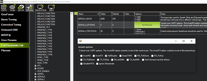
According to Mission Planner - these options are now available on 4.5.6

I don’t know if ArduPilot BLHeli pass-through is required - but I suspect not. Just to be sure, I’ve tried with both SERVO_BLH_AUTO both enabled and disabled. No difference.

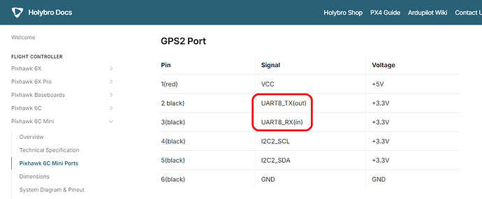
I’m using the GPS2 port (serial-4) because the ArduPilot wiki says it was tested and worked on an Orange Cube. The Holybro docs say the GPS2 port is UART8 - but I believe this is mapped to Serial4.

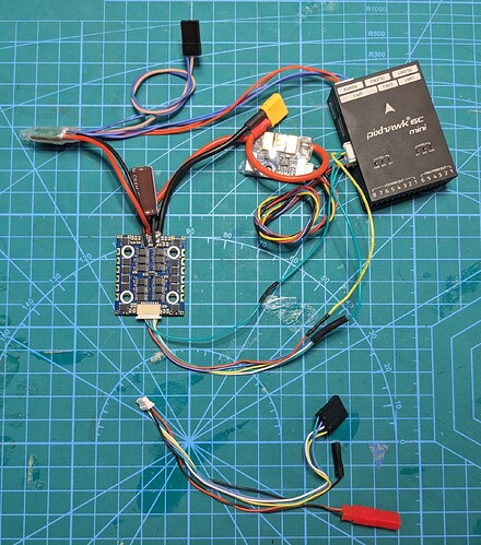
I’ve created a cable where the ESC 4 motor pins are all connected together and go to the GPS-2 TX (pin 2).

The cable also connects the ESC telemetry pin to the GPS-2 RX (pin 3).

I’ve included a wire that connects the ESC and Pixhawk ground pins.

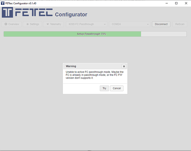
Trying the FETTec Configurator, selecting the KISS passthrough option, I get this:

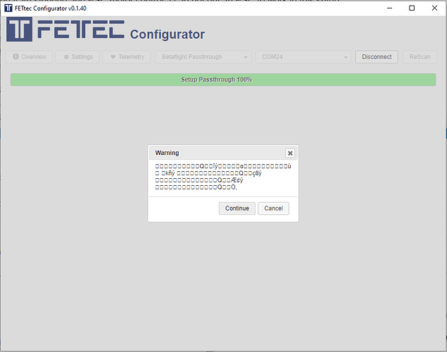
Trying the BetaFlight passthrough option, I get this:

So maybe using ArduPilot and/or a Pixhawk flight controller are still unsupported for the FETTec Configurator. I don’t know what else to try.

The ArduPilot wiki says using a USB-Serial adaptor is an option - and there’s an option for that on the FETTec Configurator. I can’t find any FETTech documentation on how to set this up properly - baud rate, options etc.

There are comments on threads about all this that mention using FTDI adaptors. I’ve read that a USB-Serial adaptor can be slightly different - so I’ve ordered a USB Serial port adaptor instead of trying the FTDI adaptors I have on hand.

I really don’t want to have to use a KISS or BetaFlight flight controller to get this FETTec ESC Configurator to work.

While BLHeli_32 is no longer supported, it supports “sinusoidal” - so FETTec doesn’t have that as an advantage. And the last version of the BLHeli_32 has a “by-rpm” setting for output PWM signaling - which is something that I don’t think FETTec supports.

If anyone has gotten the FETTec Configurator to work either with a USB-Serial adaptor - or an ArduPilot flight controller - I’d greatly appreciate some guidance.

Many Thanks!
Hi. I need to figure out, if half-duplex is working now.

I made a quick video, how it is working with a USB-Serial adapter, that does not support half-duplex. You need a diode for this:


I just tried if the passthrough is working with a attached logic analyzer with a cube orange plus and FETtec 65A. If I enable half-duplex there is no outgoing communication from the cube, in passthough-mode. If I disable half-duplex I see correct traffic on tx, but the ESC needs half-duplex for the configuration mode. Without halfduplex and 2000000baud it is not possible to reach the configuraton mode atm. I believe you will reach the configuration mode with the USB-Serial adaptor faster.

Btw. what motors are you using?

1 Like

Thank you for your kind and informative reply.

I’ve followed your video instructions:

I’m still not able to connect to the ESC.

Yesterday I just soldered on the motor leads - and I may have damaged the ESC. Now when I power the ESC, I only get one red LED, instead of the blue LED. I’m going to get a new ESC from our workshop and try again.

In the mean time - would you please answer these questions?

  1. I can’t find FETTec documentation that states the serial requirements for the telemetry connection. I’ve read in ArduPilot documentation that it requires 2M baud and half-duplex.

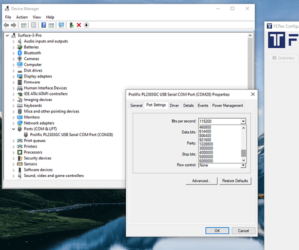
My USB-Serial adapter does not have 2M as an available baud rate. Is it possible to use a different baud rate? I’ve tried several other baud rate settings - none have worked.

  1. The diode I had available is a 1N4007. Is this acceptable?

I’m interested to see in your video that the connection for the configurator does not include any of the leads for the motor signal. My guess is that this is why these ESCs are called “One-Wire.”

The ArduPilot documentation does not address this - and actually mentions connecting the motor leads in parallel.

We have tried several motors. The one we plan to use for this project is an small inexpensive motor with spin-on props. I do not have a brand or model - but I can get it for you.

We have also tested small KDE motors on our workbench.

As I mentioned in my post, our problem has been that about 20% of the time, a motor will not start properly - it will “stutter.” Our hope is that we can fix this by changing a parameter setting in the firmware.

I look forward to hearing your replies to my questions. I will also follow up with our results.

Many thanks!

One more question, if you please:

If 2M baud is a requirement, I’ll need to find a USB-Serial adapter that supports 2M baud. Looking on line, it’s not easy to find this.

Would it be possible to say the name and model of the USB-Serial adapter that you are using?

Many thanks!

You do not need to connect the motors to flash newer firmware or configure the ESCs. But you need to supply voltage on BAT+ and BAT-.

Windows shows not all supported baud rates. I am using a cheap one with a CH340G chip. It is called “SDS011_USB2TTL_004”. I also used an Arduino UNO, where is connected Reset and GND to bypass the Atmel and other dongles. Some USB-Adaptors have RX and TX swapped. Maybe you can check that.

If you use half-duplex then the baudrate should be 2M baud (Connection via diode is also half-duplex, because the ESC sends half-duplex). If you use full-duplex its 500000 baud.
1N4007 is exactly what I used in the video and should work.

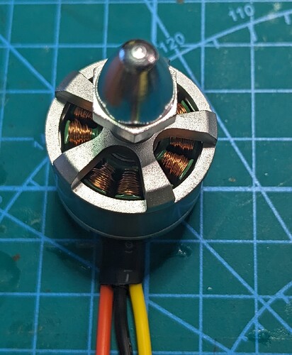
Please also check if the motor-screws are to long and connect the phases to your frame. That can cause the random stutter.

If you supply power to the ESC without the data cable connected, do the LEDs flash?

Thank you again for your kind and informative reply.

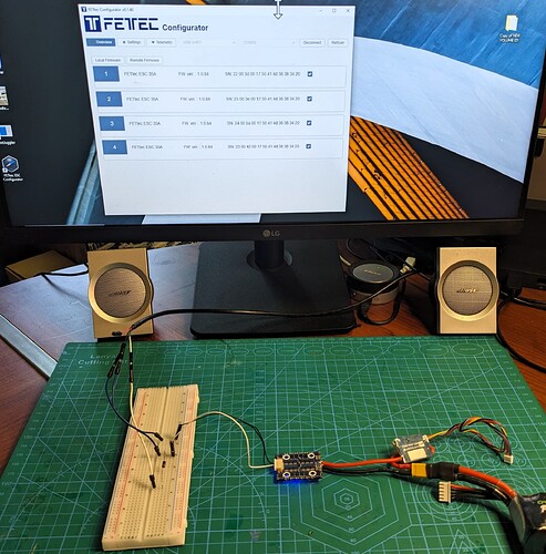
Using a new ESC, I was able to get the Configurator program working using your wiring:

I set the baud rate of my serial port to 115,200 and that worked fine. I tried several other baud rates - and they all seemed to work.

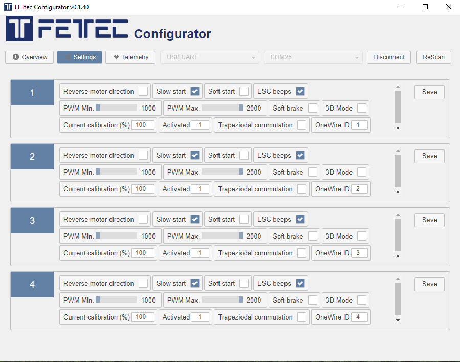
I did have to update the firmware for the settings to work. I would get dialog box warning that the serial port connection was unreliable until I updated the firmware. The firmware that came on my ESC was 1.0.84. The latest firmware is 1.0.224. That worked well - and I am able to adjust setting for all four ESC.

The problem we had with motors “stuttering” on start up was solved by removing the “slow start” feature in the configurator. Our motors also required setting the minimum motor to 6% in Mission Planner for reliable starts.

Even when setting the motor minimum to a very high setting - like 40% - the motors would still sometimes “stutter” on startup. It appears that the “slow start” feature can simply be too slow for some motors.

In my previous with 4-in-1 ESC are BLHeli_32. So I’m familiar with most of the options available. But it would be nice have a reference to study. Can you please provide a link to an explanation of all the available settings?

BTW - the red LED on my previous ESC does not blink when the data cable is detached.

Once again - thank you for being so helpful!

Hello again -

It appears we’re having a problem shorting out this ESC. We’re mounting it in a very small body - and we haven’t yet taken good precautions to insulate the electronics.

I’m used to working on much larger quads - where it’s been much easier.

Today, when I did my first motor test, it failed to spin the motor. I discovered that only 3 of the four blue lights were illuminated. I don’t know what happened - but it appears that this was why the motor test failed - I was using that ESC.

While removing the ESC to investigate, I didn’t take good precautions, and accidently shorted out something else on the ESC - and now I have no blue lights - only the red light.

Am I correct that this is an unrecoverable failure?

We’d still like to use this ESC - as any other one would have similar problems.

I’m thinking one way to protect the ESC is to apply a heavy couple of coats of conformal silicone coating. Then maybe place some kapton tape over the ESC.

Because of the heat generated by the ESC, I can’t think of any other options.

Would you have some suggestions to help us provide good electrical insulation for the ESC?

Thanks you!