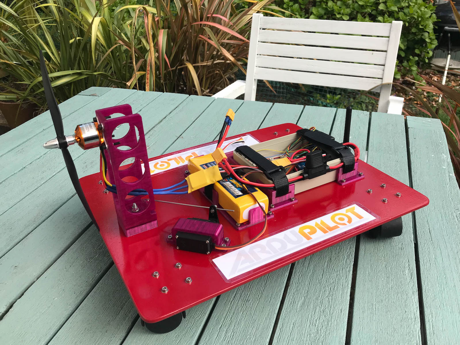
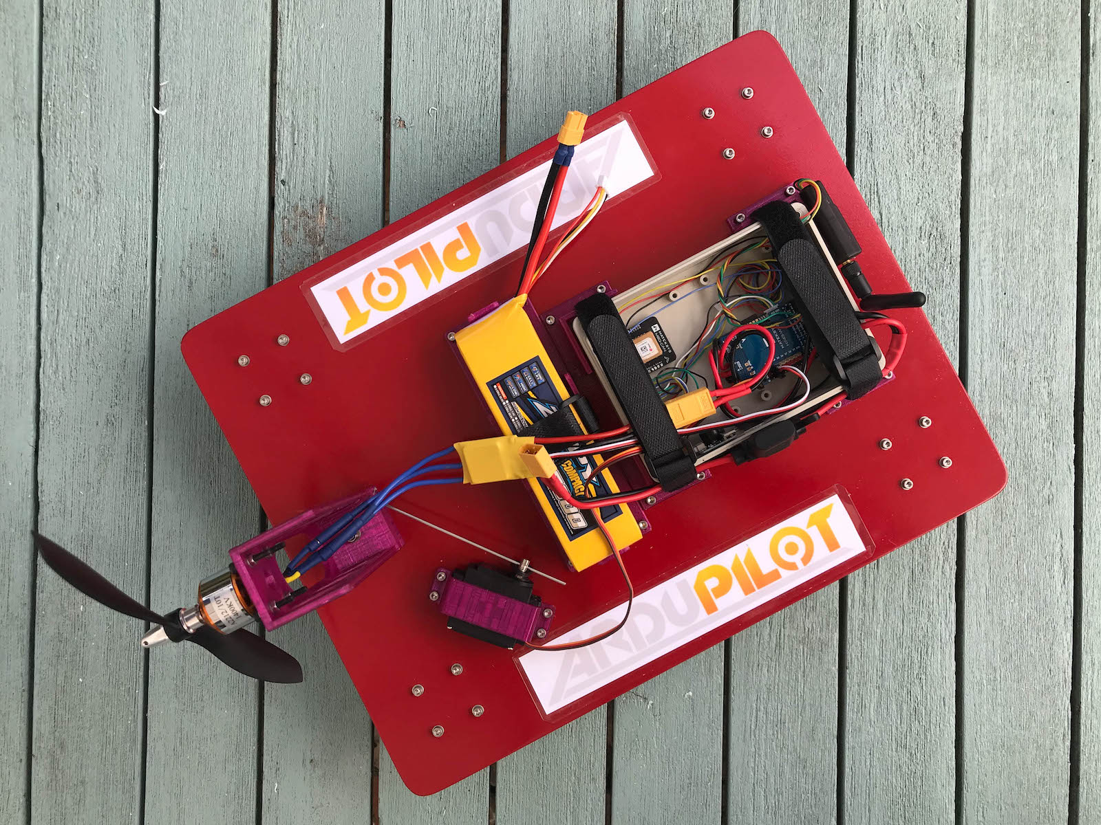
A fan car is a low cost, easy to build, vectored thrust rover. The concept and original design came from @peterbarker in this Discord post. The castor wheels make this rover interesting to control, best results are obtained using Rover 4.1.0 or higher which has updated support for vectored-thrust frames.
Parts List
- Base
- 1x 400mm x 300mm x 5mm plywood board
- 1x 145mm x 105mm x 40mm ABS project box
- Motors and servos
- 1x A2212 1400KV brushless motor
- 1x 30A brushless ESC
- 1x 8045 propeller
- 1x MG995 servo motor
- 1x 130mm control rod and connector
- Wheels
- 4x 40mm furniture castors with screw plate mount
- Electronics and connectors
- Matek H743-WING or similar ArduPilot compatible flight controller
- Matex GNSS MQ8-CAN GPS or similar GPS unit
- FrSky RX6R or similar receiver
- 3 Cell 11.1V LiPo battery
- ArduPilot compatible telemetry radio
- XT60 connectors or similar for the battery and ESC
- Bolts and bearings
- 36x M3 x 12mm hexagonal socket head cap screws
- 4x M3 x 16mm hexagonal socket head cap screws
- 40x M3 Nyloc hexagonal nuts
- 56x M3 washers
- 1x M4 x 25mm hexagonal socket head cap screw
- 1x M4 Nyloc hexagonal nut
- 2x M4 washer
- 1x 604ZZ (ID = 4mm, OD=12mm, Thickness = 4mm) bearing
- Straps
- 1x 200mm x 20mm hook and loop strap
- 2x 400mm x 20mm hook and loop strap
- Printed parts
- 4x box brackets
- 1x battery tray
- 1x servo clamp
- 1x motor bracket base
- 1x motor bracket
The motor bracket and base are based on originals kindly provided by @peterbarker . Parts were printed in PETG with a 0.20mm layer size.
FanCarParts.zip (153.8 KB)
Build
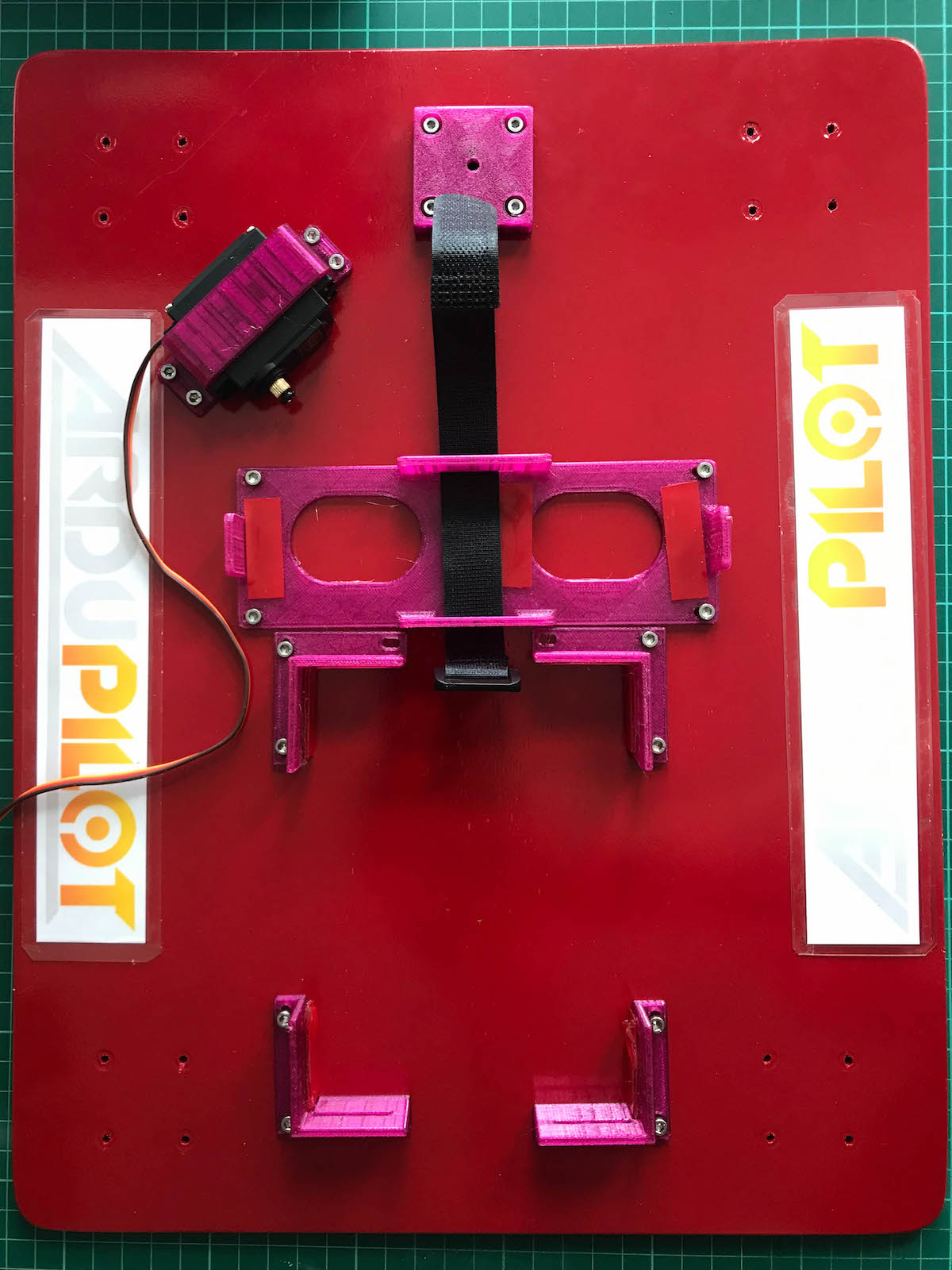
Prepare the base:
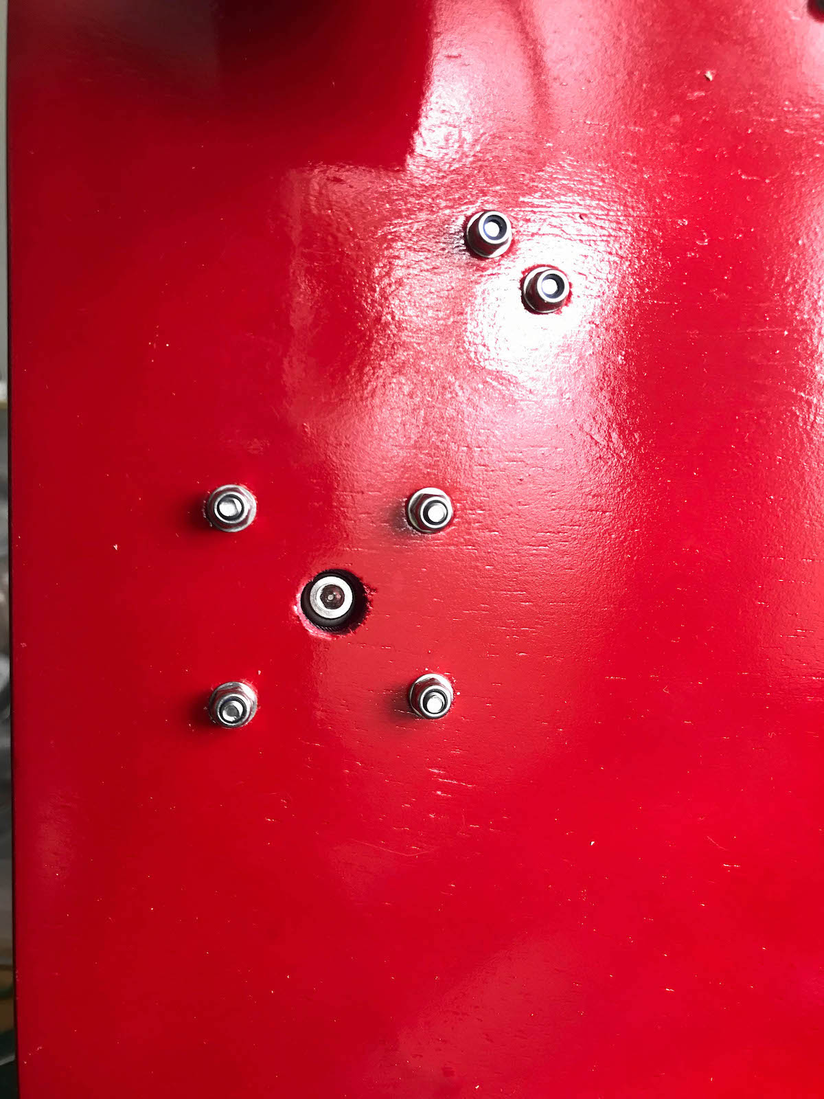
- Measure and drill holes for brackets using a 3mm bit. The hole to access the motor base retaining screw is 10mm.

Attach brackets
- Mount the box brackets, battery tray, servo clamp to the base using M3 x 12mm screws.
- Mount the motor base using M3 x 16mm screws.
Attach wheels
- Mount the castor wheels using M3 x 12mm screws.

Prepare the motor bracket
- Press the 604ZZ bearing into the recess of the motor bracket.
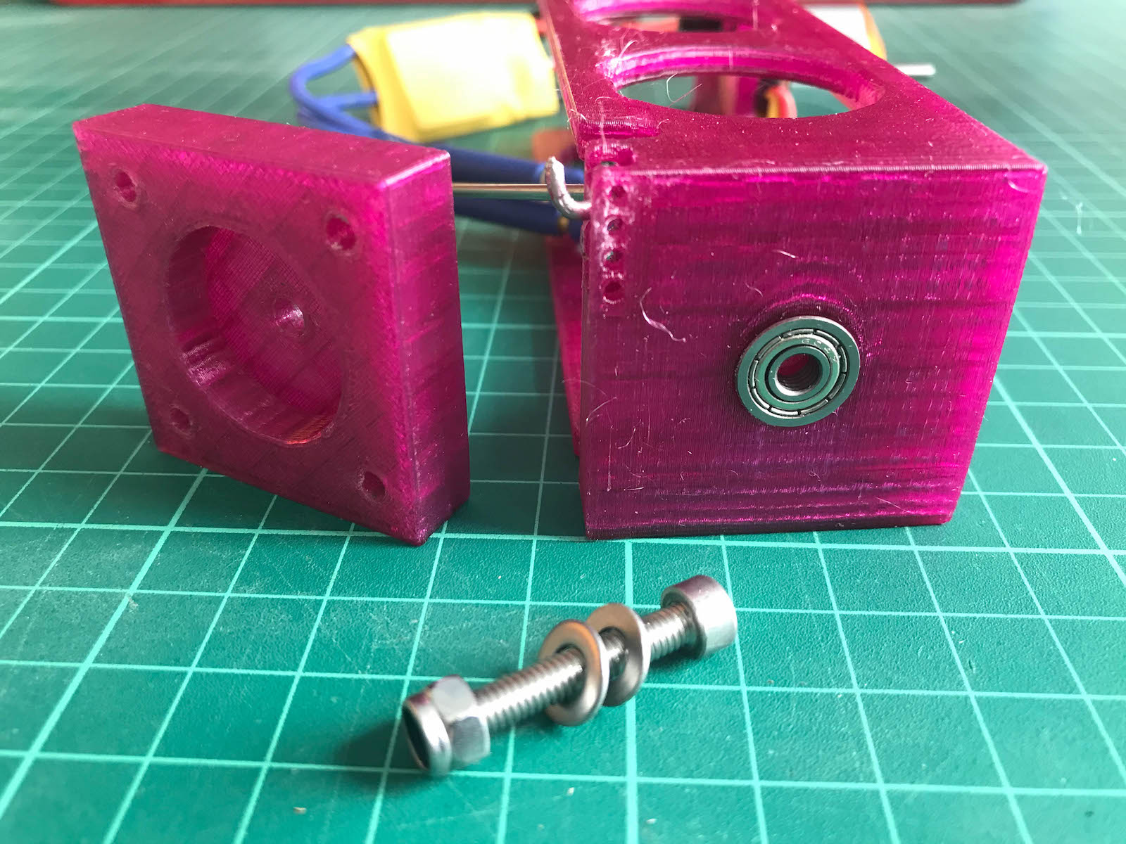
- Attach the motor to the bracket using M3 x 12mm screws.
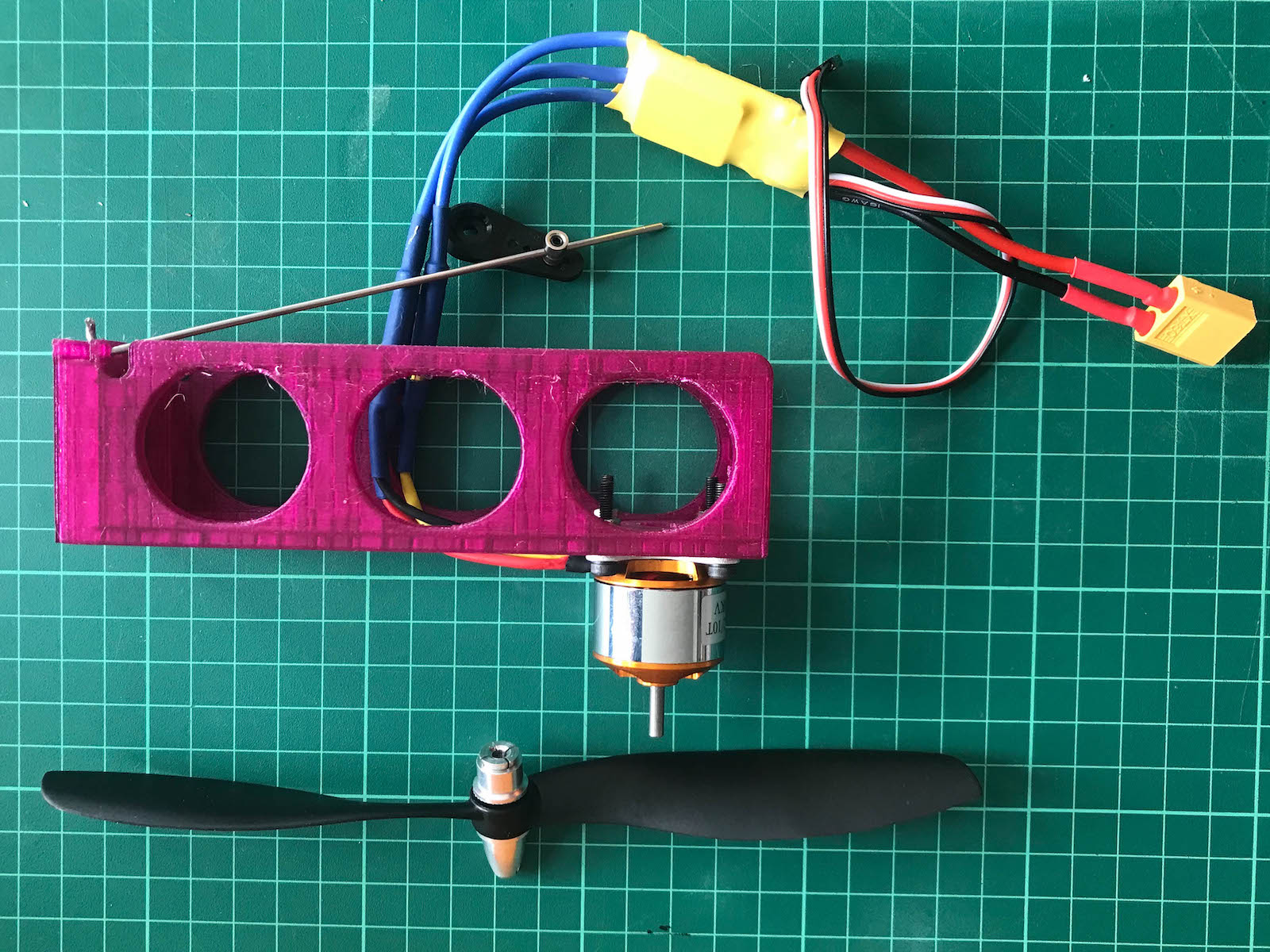
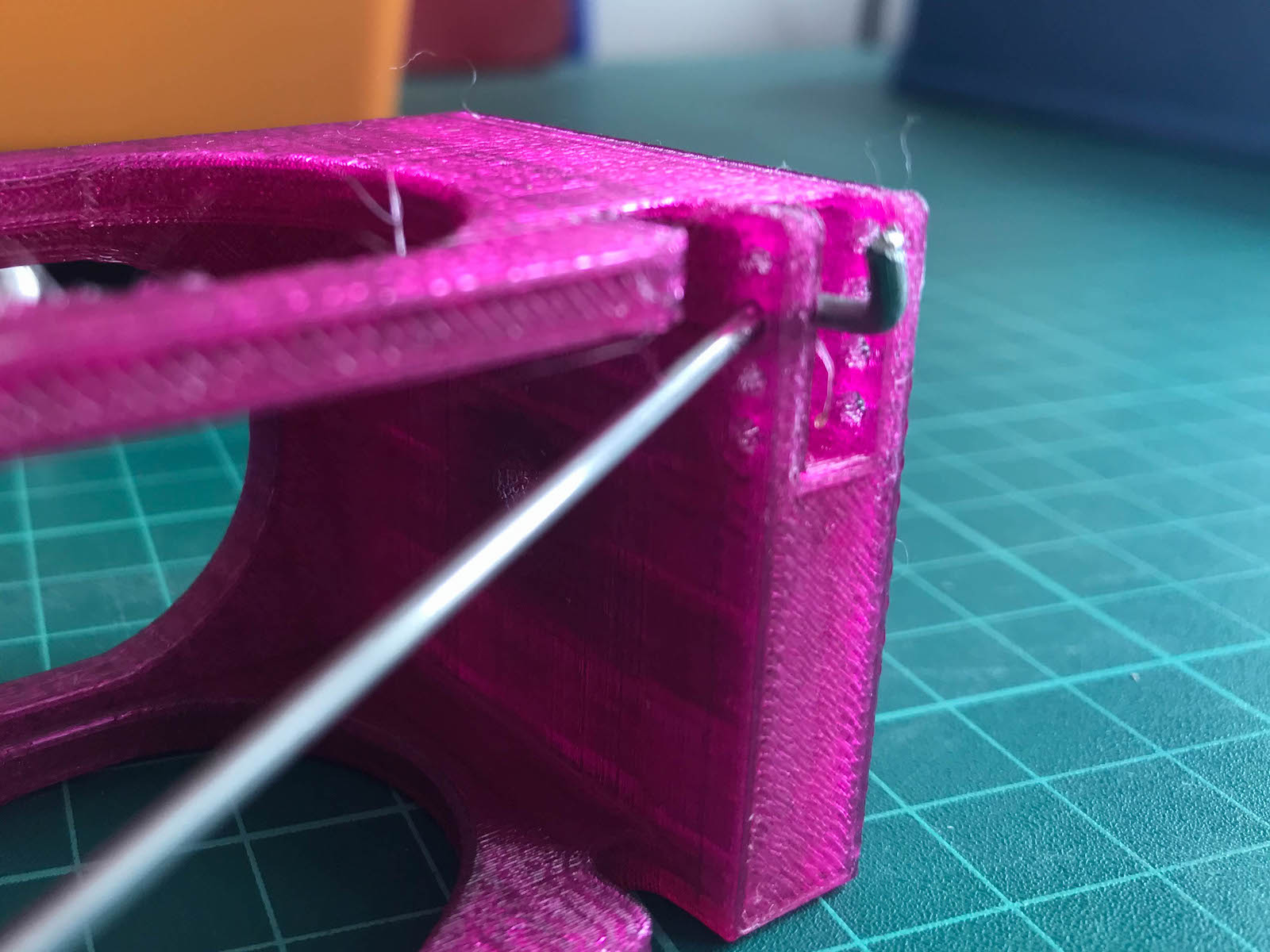
- Attach the control rod to the motor bracket.
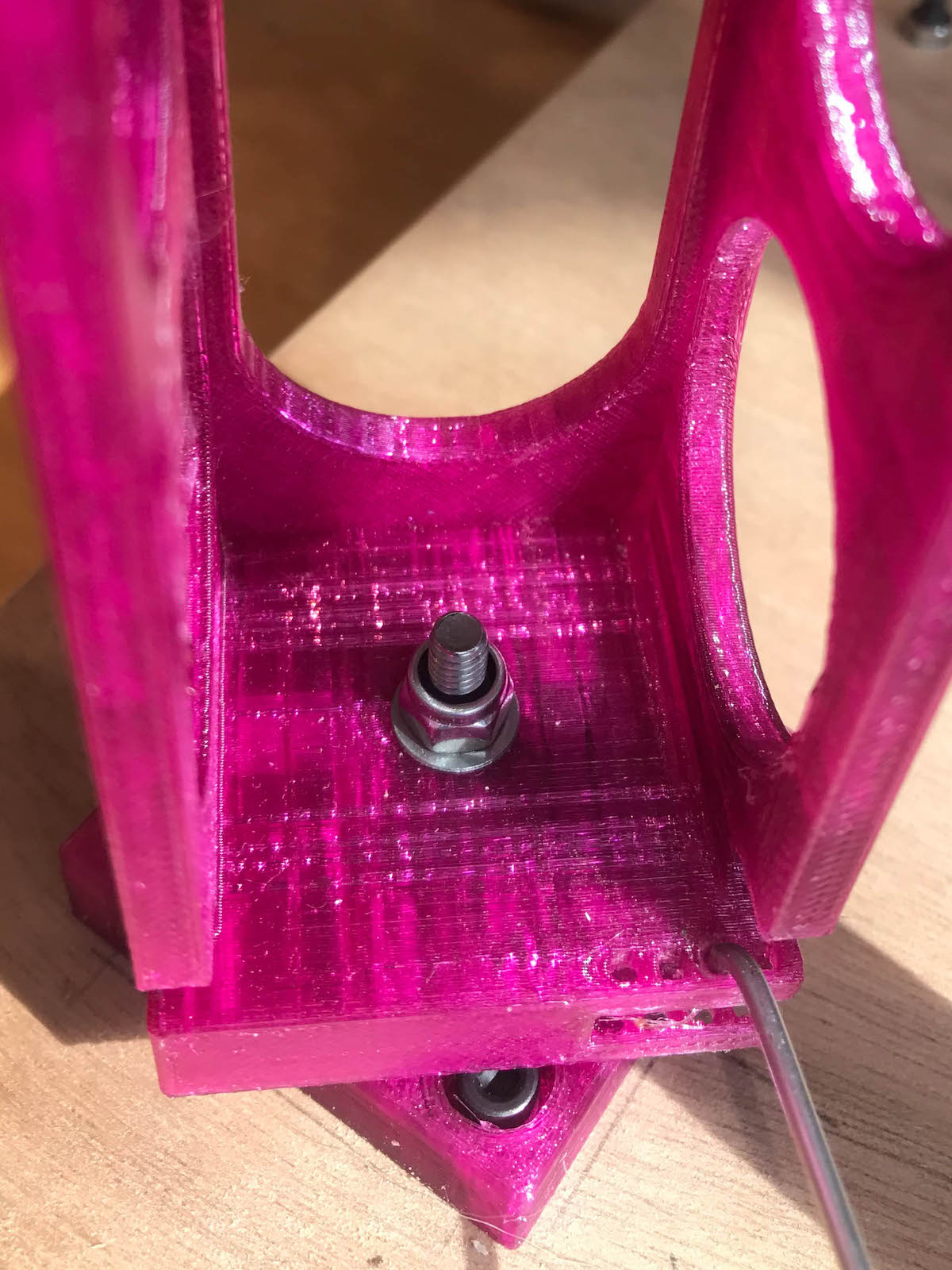
Attach motor bracket to the base
- Insert the M4 x 25mm screw through the underside of the motor base
- Fasten the motor bracket with a M4 Nyloc nut - tighten so that the
bracket is firm but still free to move
- Place a connector on the control rod and attach the control horn to the servo. The horn should be vertical when the servo is centred (1500 PWM). Adjust the connector so the motor is centred.
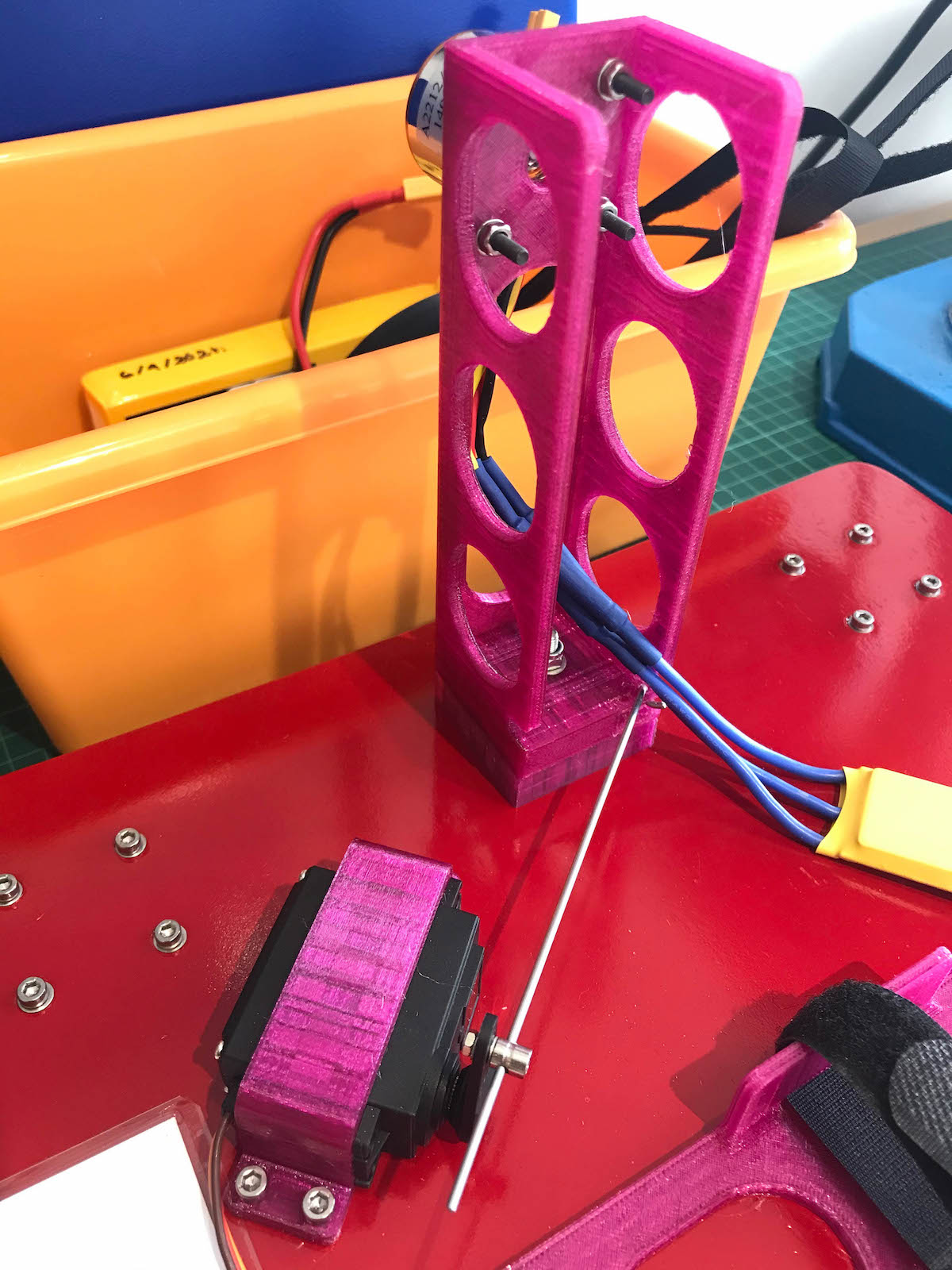
Attach the project box and connectors
- Attach the project box using straps and connect the wiring.
- Use self-adhesive foam pads on the battery tray and project box brackets to ensure a snug fit and provide vibration damping.
- Connect the steering servo to SERVO1.
- Connect the ESC to SERVO3.
Setup
The rover is configured as a vectored-thrust boat. Using the boat frame sets the AHRS fly_forward variable to false: this prevents the EKF from using the rovers’s movement to estimate heading which is important as the vehicle has poor yaw control and can easily drift sideways.
Firmware
Install Rover 4.1
Vehicle and frame
FRAME_TYPE = 2 (Boat)
RC
RC1_MAX          2000
RC1_MIN          1000
RC1_TRIM         1500

RC3_MAX          2000
RC3_MIN          1000
RC3_TRIM         1000 (No reverse)
Servo
Set the steering servo trim to centre the motor and then adjust the limits to achieve 45 degree rotation either side of centre. The servo may need to be reversed.
- Steer left => motor bracket rotates anti-clockwise
- Steer right => motor bracket rotates clockwise
SERVO1_FUNCTION  26 (Ground Steering)
SERVO1_TRIM      1500
SERVO1_MAX       2200
SERVO1_MIN        900
SERVO1_REVERSED     1

SERVO3_FUNCTION  70 (Throttle)
SERVO3_MAX       2000
SERVO3_MIN       1000
SERVO3_TRIM      1000 (No reverse)
Motors (vectored-thrust)
The vectored-thrust parameter MOT_VEC_ANGLEMAX must be set to the same deflection range as the motor bracket. This is 45 degrees.
Reducing the MOT_SLEWRATE from its default of 100 is needed to ensure good throttle response which is required for the throttle and steering tune.
MOT_SPD_SCA_BASE  0
MOT_VEC_ANGLEMAX 45
MOT_SLEWRATE     70
The throttle tune is critical for good steering and navigation control. Time spent getting the throttle well tuned will make it much easier to tune the remaining controllers.
Throttle
ARMING_RUDDER   0.0
CRUISE_SPEED    2.0
CRUISE_THROTTLE 50
ATC_ACCEL_MAX   1.0
ATC_BRAKE       0
ATC_SPEED_P     0.4
ATC_SPEED_I     0.1
ATC_SPEED_D     0
ATC_SPEED_FF    0
You may need to switch between the steering and throttle tuning steps a number of times to get the vehicle responding well. The steering tune requires good throttle control and tuning the throttle is difficult if the rover will not steer!
Steering
ACRO_TURN_RATE  90
ATC_STR_RAT_MAX 90
ATC_STR_RAT_P   0.3
ATC_STR_RAT_I   0.02
ATC_STR_RAT_D   0.01
ATC_STR_RAT_FF  0.1
Navigation L1
The frame is ‘twitchy’ - setting a long NAVL1_PERIOD helps dampen out oscillations.
NAVL1_DAMPING   0.75
NAVL1_PERIOD    15
Missions
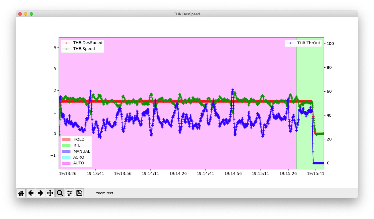
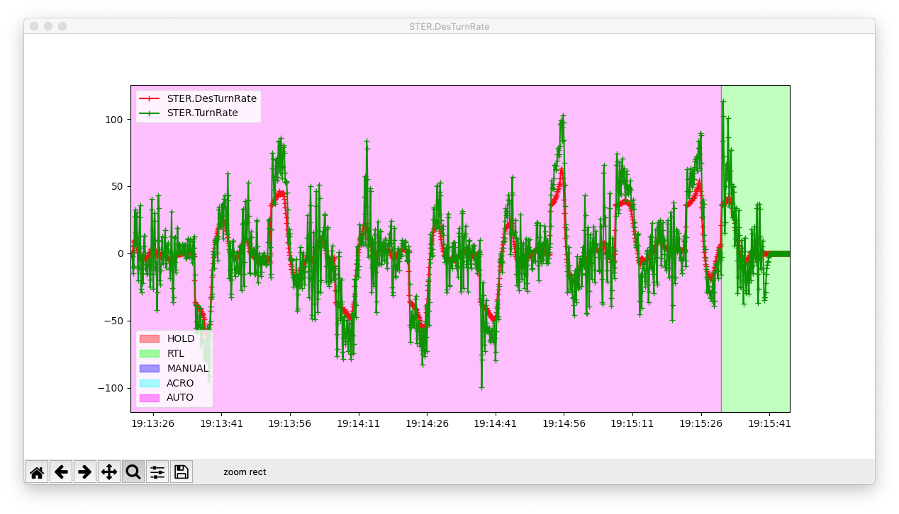
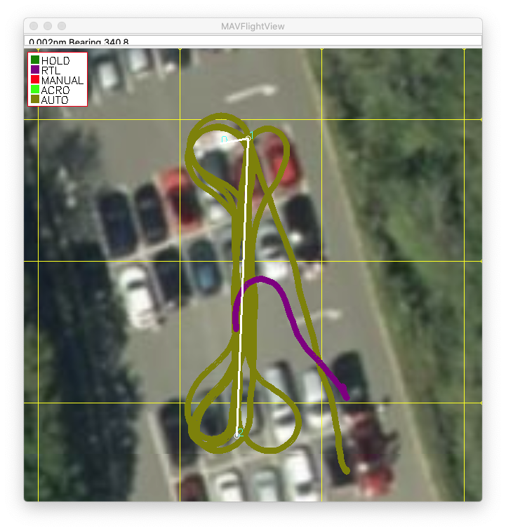
The Rover 4.1 vectored thrust controller is very effective. With a bit of tuning the fan car will run well in AUTO mode and tracks between waypoints well. The throttle and steering PID graphs are noisy - the rover constantly needs to be brought back on track, but the controller is up to it:
Throttle tune:
Steering tune:
Navigation tracks:
Simulation
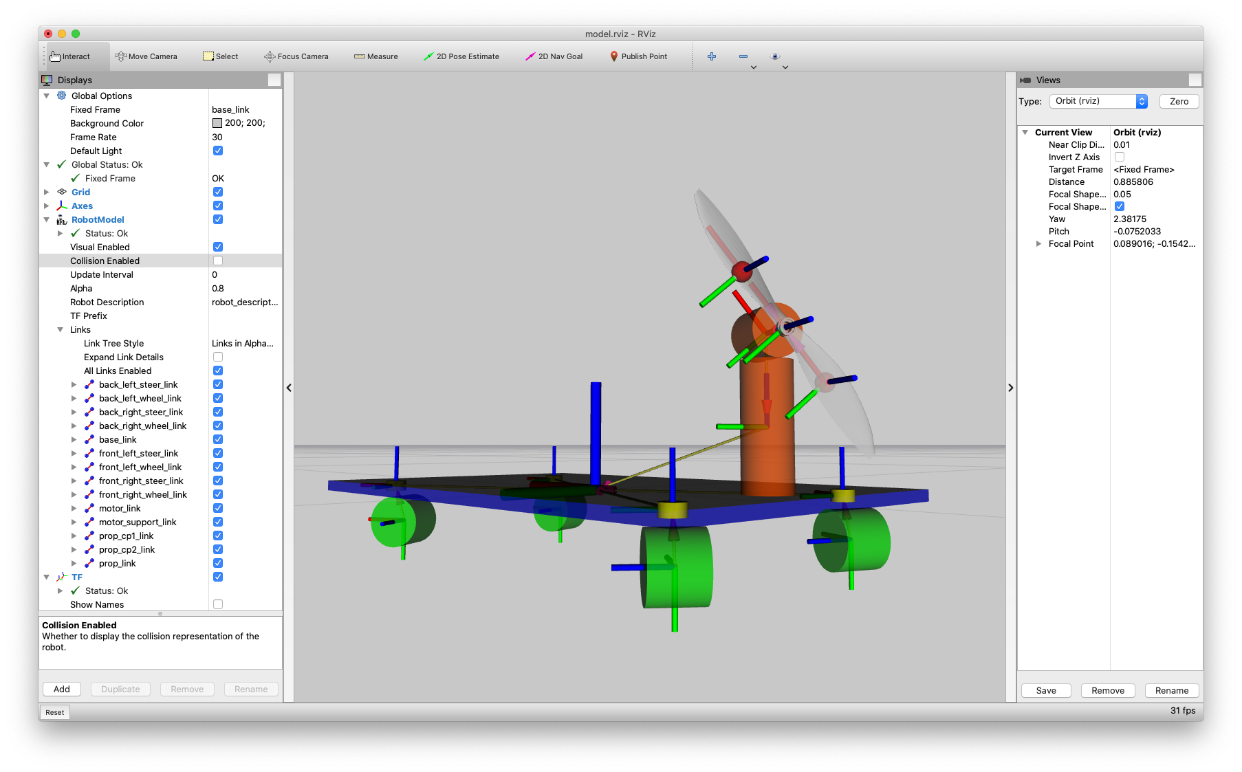
My original interest in Peter’s fan car was to see if it was feasible to control in simulation using Gazebo. It’s proving to be a useful example for tuning the physics properties of a Rover in Gazebo and testing the Gazebo - SITL/JSON interface:
- Castor wheels mean the frame is holonomic in 2D (i.e. it has no constraints on movement).
- The simulation needs to have the wheel damping and friction calibrated well. Since none of the wheels are driven, all the deceleration arises from wheel joint damping (ignoring air friction for the moment).
- The simulation needs to have the motor rotation and propeller thrust well calibrated. It turns out that the PID controller for the simulated motor needs to be well tuned otherwise the vibrations ruin the EKF (like in real life), and the propeller thrust for a given rotation speed is something that needs to be calibrated as well.
- The methods for this vehicle can be transferred to other vehicle and frame types (other rovers, boats, perhaps copters).
The clip shows the Gazebo model with the physics and simulation parameters reasonably calibrated. The simulated rover is following a similar mission and using the same parameter set and PID tune as the real rover.
The Gazebo model is available here: https://github.com/srmainwaring/ardupilot_gazebo_models.
To run the models with the ArduPilot JSON-SITL backend requires a modified version of the ardupilot_gazebo plugin that is available in this fork: https://github.com/srmainwaring/ardupilot_gazebo/tree/feature/sitl_json
 Fantastic job!