Hello, i want to find a easy solution to stop motors with external circuit in parallel ,my idea is just to link pwm signal with mosfet or transistor to the ground , I wonder if it might not destroy the pixhawk , in piaxhawk 1 hardware there is 220 ohms resistor in series with the outputs , i can not find the pixhawak 4 detailed hardware ,it should be the same thing and it can work , I want your idea on the subject
Hello @Tarek-H
Why don’t you use Emergency Stop feature provided by Ardupilot? It would be the simplest way to do that and you wouldn’t need any kind of extra hardware:
https://ardupilot.org/copter/docs/common-auxiliary-functions.html
I can testify that the Motor Emergency Stop feature definitely works as planned.
If you really need some external device, you would probably need to use some circuit with a 74LS244 or similar to properly pass the PWM signals (or disable them). Your idea of shorting the PWM outputs to ground may work but would need testing.
1 Like
it is for a specific regulation, they ask for an independent parachute with an independent engine cut-off.
I have already designed and tested components (mux) which connect in series with the pwm output, it works well but if the component fails there is a big risk, I am thinking of a simpler solution and more reliable which connects in prallel and can be detached from the main circuit that’s where my idea comes from.
1 Like
Old post, but more relevant than ever due to EU regulations and possibily other jurisdictions.
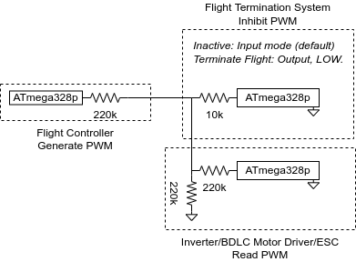
As a test, I connected a 220K resistor to an ATmega328p, which simulates an FC, and generated a PWM pulse from this MCU, and confirmed this signal to be received by a real ESC running SimonK (tgy) firmware.
Then, I connected a 10K resistor between an I/O port of another MCU and the PWM line (after the “FC” output resistor and before the ESC input resistor).
When setting the pin mode to Output, and the level to Low on the flight termination system, this seemed to effectively inhibit the PWM signal.
It might be a solution. I have no clue how other people are doing this. I would be interested to hear the viewpoints of others on this. If, for whatever reason an FTS is needed, which needs to be independent from FC, then what would be the best way to implement it? Of course some users would not use an FTS or rely on FC for flight termination, that is another topic.
The main question is: will the gate accidentally be pulled low somehow? If the FTS has some kind of failure, which for whatever reason may cause it to pull the line low, than you have just transformed your fancy vehicle into a brick.
The FTS allows preventing the vehicle from leaving the flight volume whenever for whatever reason the FC is not able or unwilling to respond to any commands, and for whatever reason is about to breach the flight volume. The price you pay for this feature increased risk of unintended brickification during flight!
@joelmeijering, your FTS will work if everything is shown in your diagramm.
But if the FC has no such big serial resistor in line of the output it will not work.
By your circut you only change the load on the output pin from around 220 kOhm to around 10 kOhm. So if for example the serial resistor on FC side ist just around also 10 k Ohm than the PWM input level to the ESC is only half way but still available. If the serial resistor on FC side is lower than 10 kOhm the PWM input level to the ESC ries more.
Reducing the 10 k Ohm on the FTS can cause damages on both outputs the FC and the FTS output. Never combine two active outputs with low inline resistors.
Always better solution is to cut the line between FC and ESC for example by a AND logic as mentioned by @xfacta.
1 Like
That is just working almost by accident. You are just loading down the signal until it’s unacceptable for the ESC.
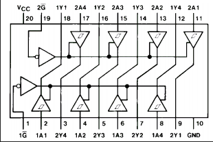
Have you even thought about the ICs available such as the 74LS244, for example, since they have an enable signal that will either allow or cut off the outputs. That’s just one of several such ICs that sprang to mind.
Your system of just loading the signals may not work on many of the non-cheap flight controllers since they already have buffers built in, like the 244 or similar. They would have more capacity to overpower such load resistors and continue working regardless, or at least unreliably.
PWM is not necessarily in use, so you’d need to test with other protocols. What about CAN or serial (onewire) based ESCs?
And it all depends on what flight termination really means and what such regulations actually say. It could be a matter of disabling the receiver to force RTL or Land. RTL is considered flight termination in a lot of circumstances. Weight has to be given to the argument that killing motor outputs, or even just landing, could be much more unsafe than doing RTL. It would be better to ensure a radius and altitude fence is set, plus there are stay-in and stay-out zones - and you have FENCE_ENABLE,1 With that simple configuration you cant even arm and fly in any mode until there is a good GPS 3D fix and Home can be set. If you could demonstrate that working (and it does work) then technically there would never be any need to kill motor outputs.
I think some of these things are dreamed up by politicians or administrators that have no idea what they are dealing with - imagine having “flight termination” for all cars, where initiation means all control is suddenly lost (including brakes) and the vehicle does whatever its momentum dictates.
/end rant
2 Likes
According to the FMUv5 spec, regarding some outputs, among which PWM, it states: “(…) provide bidirectional transceiver buffering with TXS0108E and 220 ohm series resistors similar to FMUv2 (…)” [1].
On an FC with FMUv6C, I noticed that instead of having a single TXS0108E per 8 PWM outputs, it has 2x 4-bit buffers per 8 PWM outputs, marked “7MP”. Conforming to the FMUv5 spec, it also has the 220 ohm resistors. Note: These resistors are between the STM32 MCU and the buffer IC. The PWM connector is directly connected to the buffer IC.
According to TI, regarding the TXS0108E: “Each A-port I/O has a pull-up resistor (RPUA) to VCCA and each B-port I/O has a pull-up resistor (RPUB) to VCCB. RPUA and RPUB have a value of 40 kΩ when the output is driving low. RPUA and RPUB have a value of 4 kΩ when the output is driving high.”
@xfacta, @Juergen-Fahlbusch: Regarding the method of loading the PWM output lines to terminate flight: The ATmega 328P will pull all IO lines low when powered down. So this will bring the vehicle down when the FTS loses power. Not ideal!
Instead of the buffer IC suggested by @xfacta, It may be possible to pull the PWM line high instead of low. Perhaps in combination with a diode to prevent the FTS sinking any current when the FTS is powered down. This avoids needing a buffer IC. As @xfacta pointed out, this is also sensitive to any differences between FCs and may not work for non-PWM setups.
However, adding active components between the FC and the FTS introduces a failure mode where the vehicle would brickify itself when the FTS is for whatever reason powered down. I think it makes sense in more complex vehicles to put all components essential for flight on a single 5V rail, and anything secondary on other rails. In such a scenario using a buffer IC would introduce an additional failure mode, unless the FTS was on the main 5V rail.
@xfacta: Regarding the “why” around FTS: The FTS is a second line of defence for containment breaches.
There are no single fault conditions that require an FTS.[2]
In the following scenario, FTS is needed to guarantee containment:
-
RC link lost. (no backup RC link)
-
Any of the following:
- Undetected compass, undetected GNSS, undetected IMU failure
- (Position) control loop failure
Note: If a Compass or GNSS failure is detected, AP may disable them and perform inertial landing, I believe. In the case of a multirotor, is unlikely to result in containment breach depending on wind strength, vehicle characteristics and safety buffer size. However, in some cases I have observed toilet bowling and other effects when the compass was not marked unhealthy, even though it was.
Note: IMU failure can be picked up and recovered from by switching to the other IMU. So it is unlikely to cause a failure.
For all other failures, Ardupilot can at least ensure containment is not breached. Operator intervention may be needed to prevent damage. Lastly, in some cases, the operator cannot prevent damage, but containment is still preserved.
Sources:
[1] The PX4 Reference Flight Controller Design page contains a link to the pinout (FMUv5_stm32_pinout.xlsx) of the FMUv5 standard
[2] uas-risk-management.txt (1.3 KB) (written by me)