Ive built a tarot fy690s hexacopter with 4108 tarot motors and 13 in props. each motor consumes a max of 12.8 A, so i made a 6s7p battery out of samsung 30q cells, capable of 15 amps per cell for a max theoretical output of 105 amps, and a total theoretical capacity of 21000mah, yet im only getting less than 2 minutes of flight time before the batteries sag to just above 18v and trigger the failsafe. Im thinking its my BMS, is there anything else it could be? additionally the motors seem to be under performing, requiring more amps to create the rated thrust.
Those cells should use these settings for 6S
BATT_FS_CRT_ACT,1
BATT_ARM_VOLT,17.30
BATT_CRT_VOLT,16.20
BATT_LOW_VOLT,16.80
MOT_BAT_VOLT_MAX,25.20
MOT_BAT_VOLT_MIN,15.00
The other thing to check is the accuracy of your voltage monitor at about 16.0 volts, and your charger settings.
There’s no denying that copter is struggling with the thrust. Motor outputs go to maximum when trying to arrest that descent. These look odd:
MOT_PWM_MAX,1932
MOT_PWM_MIN,1065
MOT_SPIN_ARM,0   // shoud be about 0.1 for arming indication
What ESCs have you got?
To get the same thrust as a 6S Lipo, I think you need to up that Liion 30Q pack to 7S or 8S and you could probably go down to 6P.
From the datasheet
- 3.1 Nominal discharge capacity
3,000mAh
Charge: 1.50A, 4.20V,CCCV 150mA cut-off,
Discharge: 0.2C, 2.5V discharge cut-off - 3.2 Nominal voltage 3.6V
- 3.3 Standard charge CCCV, 1.50A, 4.20 ± 0.05 V, 150mA cut-off
- 3.4 Rapid charge CCCV, 4A, 4.20 ± 0.05 V, 100mA cut-off
- 3.6 Charging time Standard charge : 180min / 150mA cut-off
Rapid charge: 70min (at 25℃) / 100mA cut-off - 3.7 Max. continuous discharge
(Continuous) 15A(at 25℃), 60% at 250 cycle - 3.8 Discharge cut-off voltage
End of discharge 2.5V
Ive got hobbywing 30amp platinum pro escs
You should be able to use
MOT_PWM_MAX,2000
MOT_PWM_MIN,1000
and do the semi-automatic ESC calibration.
Recheck your
MOT_SPIN_ARM and MOT_SPIN_MIN after that.
Also ensure you are NOT using the bullet connectors to come already fitted to those. Properly solder and heat-shrink the motor wires.
do the bullet connectors increase resistance? and wont i damage the batteries if i go that low?
The bullet connectors have a habit of heating and losing their tension, then come apart during flight.
Also the wires tend to break off right where they enter the connector/solder.
You could use these to be a little more conservative with the battery voltage (for the cells you have now)
BATT_ARM_VOLT,18.50
BATT_CRT_VOLT,17.40
BATT_LOW_VOLT,18.00
MOT_BAT_VOLT_MAX,25.20
MOT_BAT_VOLT_MIN,16.20
but you wont fix the thrust issues unless you change the pack to 7S6P (same number of cells and weight as now), or maybe even 8S (extra weight).
Use this spreadsheet to determine the correct voltage levels, for your 30Q cells → you can choose LiIonSS for a 2.7v per cell cutoff, or change it to 2.5v per cell cutoff as listed in the 30Q datasheet.
Will the motors tolerate 7s? Theyre rated to 6s.
I was thinking about that
- the rating is for 6S Lipo voltage which is maximum 25.20 volts
- the maximum 7S LiIon 30Q voltage is 29.40 volts
Only 4.2 volts increase, and the motor voltage rating is only about the insulation properties of the enamelled copper wire, and the expected performance. It’s not like you are doubling the voltage, causing a break-down of the insulation.
With the voltage sag of the LiIon cells the motors will NEVER see that higher voltage, so I believe the motors would be safe.
It’s more likely the ESCs would have an issue and you might be better off getting something that is 8S capable.
The old version of those ESCs, the Hobbywing Xrotor 40A was the indestructible go-to ESC for many years, I’m sure many people tried to run them on more than 6S or under horrible conditions( but I cant say for sure…)
Im still getting way more voltage sag than i should be even if i was drawing a full 10 amps per cell i should only see 2.8 volts of sag. Im getting 4+.
There must be a problem with connectors and wiring if the battery cells are in good condition.
What is you charger set to?
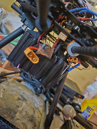
Have you got a couple of photos of the battery pack and wiring from there to power brick and the ESCs?
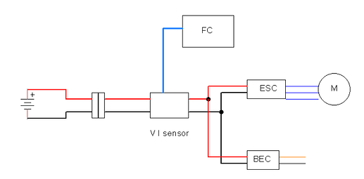
There should only be ONE connector, like an XT90 for example, between the battery and everything else.
Charger is set to 2A and charges to 24.5 volts before the bms cuts it off.
Cells are from 18650batterystore.com
There is a bec in between the battery and the pdb.
Ill get pics of the battery tomorrow.
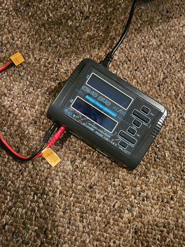
What charger have you got?
I think it should be charging to 25.2 volts for your 6S Liion pack.
24.5 volts will only be about 75% TO 80% capacity.
Maybe include a schematic or diagram/drawing of your power wiring. It should be something like this
I see a couple of problems right away.
- that blue crimp connector - should be illegal to be within a 10 metres of any aircraft of any sort! All connections need to be soldered and heatshrinked.
- is that gold anodized tube mount secured correctly?
With that charger can you check and adjust the LiIon charge settings?
I would always use balance charge - especially for the LiIon packs since cells in the middle of the pack can charge and discharge very differently to cells at the outside of the pack due to temperature.
Even with our Lipos I’ve taken to only using balance charge, except when the pack has just been used and we want to use it again soon, then we give it an ordinary charge or fast charge.
The gold anodized tube mount is mounted correctly.
I come from the automotive world where crimp connectors are standard. Ill solder and heat shrink it then. The balance plug on my bms doesn’t connect to the balance plug on my charger. The charger always says “battery disconnect error” once it hits a little above 24.5 volts so i assumed it was the bms cutting it off. Ill also fly it tomorrow and take a look at the pack with my thermal camera and see if there are any weird hot spots going on.
I have build a 6S Li Ion battery myself without any BMS but balance leads. Each cell charges up to 4.2 V and I do Balance charge only. Charging stops at 25.2V. It works perfectly each time. It is used in a plane single motor.
You probably are pulling a lot less current than i am with my multirotor
Heres the cable. Black is warm white is cool theyre not hot to the touch but you can tell the bms is warm.
I suggest you test the cells, there are lots of fake/rebranded cells out there that do not perform according to the datasheet of the real thing.
Test a cell or the pack using a digital load.
Did you get your cells from a reputable seller or ali express?


