Ego Z6 Autonomous Mower Conversion

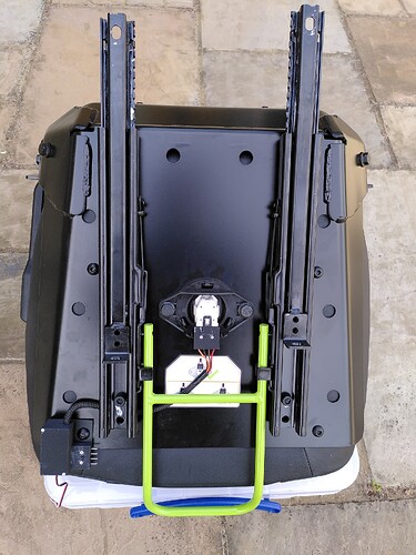
They’re 1" TV aerial brackets that already have the 90 degree bend. All I had to do was shorten them a bit so the horizontal part was about level with the top of the seat.

I’m in the UK and got them from Screwfix but there’s probably something similar available where you are:
cranked aerial mast

Yes, I 3D printed end caps and also some collars to keep the tubes rigid. Here’s the STL files:
EgoTubeBits.zip (13.0 KB)

1 Like

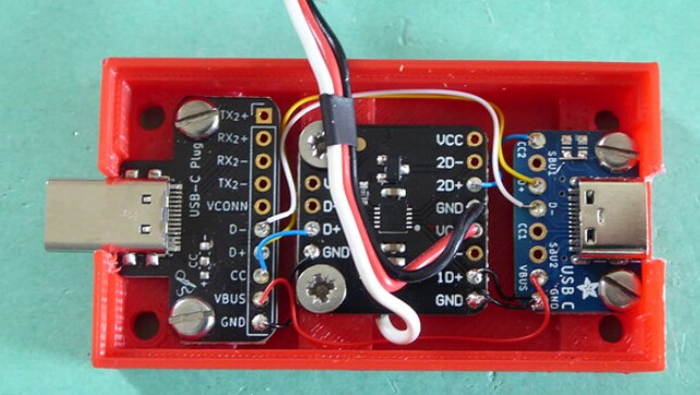
Here’s my very crude (sorry) wiring diagram for the master side Ego Hall emulator. The slave side is the same but without the ESP32 or PSU (see the photo in previous post).

Parts are not critical but there are a couple of things to note:

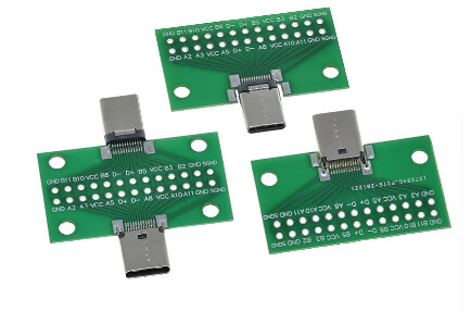
Any USB C plug and socket will do but make sure there are no pulldown resistors on the CC line or no messages will be sent.

I used this PSU module because it has an enable input. The 20k resistor connected to this pin will shut it down when VBUS drops below about 12V. This is important because there is 5V on VBUS when the mower is switched off (VBUS is about 15V when the mower is running). This emulates the behaviour of the EGO Hall sensors.

I used this switch module because I already had it but any bidirectional FET switch should work. This one is very cheap though and has a built in 3.3V regulator.

The Schottky diode feeding the ESP32 is necessary to prevent the Ardupilot from being back-powered via USB when programming the ESP32.

The 100 Ohm resistors in the data lines probably aren’t necessary but they offer a degree of protection against conflicts on the USB bus.

2 Likes

Awesome! Thank you. Much appreciated.

I will blatantly ‘steal’ your work to automate my Z6.

Did you make any progress there? Can you please share which values need changing?


On a general note: I have now three hours on the EGO Z6; it is not as easy to control, more so lacking the accuracy I have with my CubCadet ZT2… which might explain the trouble adjusting/tuning the turns. Different lever positions seem to achieve the same turn. E.g. a stationary left turn may need half back left, centre right lever, or full back left and a quarter forward right… really weird. In contrast the ZT2 produces exact turns with the same lever positions. (Lever = lap arm.)


For those who are using VScode and PlatformIO, the platformio,ini below results in a successful compile (at least on my Linux OS); please note to add #include <Arduino.h> at the beginning of the C file. I also changed:

byte messCntr,leverState;

to

uint8_t messCntr,leverState;

platformio.ini:

[env:esp32doit-devkit-v1]
;platform = espressif32
platform = https://github.com/Jason2866/platform-espressif32.git#Arduino/IDF5
board = esp32doit-devkit-v1
framework = arduino, espidf

PlatformIO is still on the Arduino-ESP32 2.x core, hence, the Tasmota fork is required.

Compile result:

 *  Terminal will be reused by tasks, press any key to close it. 

 *  Executing task in folder EGO_Automation: platformio run 

Processing esp32doit-devkit-v1 (platform: https://github.com/Jason2866/platform-espressif32.git#Arduino/IDF5; board: esp32doit-devkit-v1; framework: arduino, espidf)
-------------------------------------------------------------------------------------------------------------------------------
Verbose mode can be enabled via `-v, --verbose` option
CONFIGURATION: https://docs.platformio.org/page/boards/espressif32/esp32doit-devkit-v1.html
PLATFORM: Espressif 32 (2024.6.10+sha.5036bba) > DOIT ESP32 DEVKIT V1
HARDWARE: ESP32 240MHz, 320KB RAM, 4MB Flash
DEBUG: Current (cmsis-dap) External (cmsis-dap, esp-bridge, esp-prog, iot-bus-jtag, jlink, minimodule, olimex-arm-usb-ocd, olimex-arm-usb-ocd-h, olimex-arm-usb-tiny-h, olimex-jtag-tiny, tumpa)
PACKAGES: 
 - framework-arduinoespressif32 @ 3.0.1+sha.9736e2b 
 - framework-espidf @ 3.50104.0 (5.1.4) 
 - tool-cmake @ 3.21.3 
 - tool-esptoolpy @ 4.7.3 
 - tool-mklittlefs @ 3.2.0 
 - tool-ninja @ 1.7.1 
 - tool-riscv32-esp-elf-gdb @ 12.1.0+20221002 
 - tool-xtensa-esp-elf-gdb @ 12.1.0+20221002 
 - toolchain-esp32ulp @ 1.23500.220830 (2.35.0) 
 - toolchain-xtensa-esp32 @ 12.2.0+20230208
Warning! Arduino framework as an ESP-IDF component doesn't handle the `variant` field! The default `esp32` variant will be used.
Reading CMake configuration...
Warning! Flash memory size mismatch detected. Expected 4MB, found 2MB!
Please select a proper value in your `sdkconfig.defaults` or via the `menuconfig` target!
LDF: Library Dependency Finder -> https://bit.ly/configure-pio-ldf
LDF Modes: Finder ~ chain, Compatibility ~ soft
Found 25 compatible libraries
Scanning dependencies...
No dependencies
Building in release mode
Compiling .pio/build/esp32doit-devkit-v1/src/main.cpp.o
Linking .pio/build/esp32doit-devkit-v1/firmware.elf
Retrieving maximum program size .pio/build/esp32doit-devkit-v1/firmware.elf
Checking size .pio/build/esp32doit-devkit-v1/firmware.elf
Advanced Memory Usage is available via "PlatformIO Home > Project Inspect"
RAM:   [          ]   3.8% (used 12388 bytes from 327680 bytes)
Flash: [=         ]   6.2% (used 258457 bytes from 4194304 bytes)
Building .pio/build/esp32doit-devkit-v1/firmware.bin
esptool.py v4.7.3
Creating esp32 image...
Merged 2 ELF sections
Successfully created esp32 image.
================================================= [SUCCESS] Took 6.30 seconds =================================================
 *  Terminal will be reused by tasks, press any key to close it. 

I will sort out the warnings later, which is config related, the sweat was in getting this to compile.
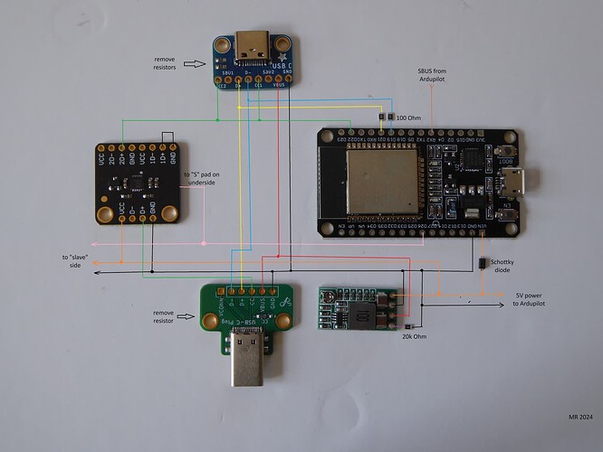
That wiring plan is not so crude! This includes some details that I wasn’t planning on, but once again, your experience will save me pain. Did you surface mount those resistors and the diode to a Printed Circuit Board, or just use old fashioned inline resistors?

I did use surface mount components but I just soldered one end to the board and a wire to the other end, apart from the 20k resistor which has both ends soldered to the underside of the PSU. Unfortunately I didn’t take any photos before I put everything on the mower. The 100 Ohm resistors are on the USB socket breakout and the Schottky diode is soldered to the Vin pin of the ESP32 board.

1 Like

@MartinRob

Thanks for that explanation.

In the US, I found the exact female breakout board, linked below, and a comparable male breakout board also from adafruit. Most breakouts only have 4 pinouts, and most are made for the end of a cable, not for screw down mounts. The screws should help hold it in place which may be better for our mower level vibrations.

1 Like

What are its specs, please? Thanks.

All I found where these, which should work too and do not have any resistors on them that need removing:
https://vi.aliexpress.com/item/1005006968681474.html
image

@Bob_Croucher That Adafruit male breakout is very neat, I haven’t seen it in the UK so I used this one

@Max_G if you use those boards with the full pinout make sure you wire to both sets of pins or the USB cable will not be reversible.
Any Schottky diode will do so long as it can handle the EPS32 current, which isn’t very much. It doesn’t really even need to be Schottky as Vin only goes to the 3.3V regulator so the voltage drop isn’t important. I used a 1N5819.

1 Like

Hi Bob, do you want to tell where you are at with your mower automation?

I also bought one of these GO Z6 mowers and have ordered parts, and once assembled will test the config and then 3D-print cases for the electronics.

I had a look at Martin’s code and am impressed with how he figured out the EGO protocol.


My general question to the forum, has anyone figured out other messages of the EGO mower?
I am in particular interested in battery-related messages, to eventually send the mower “home” to recharge by itself.

I have been motivated to get back into Ego automation after a 2 year hiatus (multiple deaths in my family).

The work Martin did on reverse engineering the USB controllers is awesome and amazing. In regards to progress, I recently created the support mount, printed the box, ordered some new electronics to mimic the controllers in the same way Martin did, but I haven’t fired up a soldering iron yet to start wiring everything. I’ll try to take a few pictures as I go to post here.

My degree is in Math, but I have worked as a game programmer for decades, for Disney and more recently Warner Brothers. To dive into the real Electrical Engineering stuff, I usually have to consult my EE friend. My experience with robotics is as a volunteer mentor for a high school FIRST robotics team since 2012. I’m excited to actually get the mower running and see how the RTK works. I’m pretty familiar with motor control theory concepts, so it will be interesting to see how controllable the mower is spatially.

In regards to the battery level, I bought a cheap Logic Analyzer and saw the values for the controllers come through, but I really wasn’t looking for other data. This info would certainly be useful. I’m sure they come around on that same channel, but figuring out how might be challenging, since the controller packets are binary. The general packet arrangement that Martin laid down may help us decipher it all though.

1 Like

Yes, battery level is the one thing you really need to know when the mower is out mowing and is the next thing I want to get working.

You are right Bob, that the messages from all the mower modules are present on the bus at the Hall sensors. I’ve been considering replacing the SBUS link between the Pixhawk and the ESP32 with CAN bus since they both have CAN controllers. This would then enable 2-way communication.

I’ve done quite a bit of message probing and there appears to be only 10 distinct message IDs:

0x01/0x02 are the control lever positions derived from the Hall sensor values. These fooled me for a while because I thought they were the messages I needed to emulate.

0x03/0x04 appear to be motor speed or power amongst other things

0x09 comes from the battery box, byte 7 of this message is the battery percentage that we need

0x11/0x12 are from the Hall sensors as we know.

0xC0 I haven’t worked this one out yet

0xC1 comes from the front power display and just contains the brake on/off state

0xCC comes from the display module and contains the mode (standard/sport/control), blade and motor settings and lights on/off state

I will put everything I’ve worked out into a document at some point and then we can add to it if we find something else.

Thanks for the update…
… and I am sorry for your loss.

Yes, I get it, when spanners are thrown in the works.
I started automating, then stopped, then got a CubCadet ZT2 and wanted to automate that; fabricated all metal, brackets, boxes, sensors, but did not finish on my self-imposed deadline, after which I would continue building my house. :slight_smile:

I drive an EV, have tons of solar, which enables me to drive at no fuel cost (Tires are still 3 Cent/km.). I bought a 2.5t digger, also electric, same here, zero cost fuel.
While filling the ZT2 with petrol, petrol splashed over my leather gloves, which gave me the sh!ts to the point that I had enough; I went and bought (of course) an electric mower.

This happened on June 15, and here I am, back in the business of automating it… in my ‘spare’ time, as I have interrupted building the house for some land, and more so, fire prevention management.

I do code, but not to the level you and Martin do; funnily enough, I am good at applying standards and good coding practices :slight_smile:

Some of the parts arrived today; I chose to use the same parts Martin listed, simply to ensure success by creating an identical copy, which would, should the need arise, help troubleshooting greatly.
… in the process of designing the cases…

I wonder what these (magic) numbers represent in lines 126 and 135:

    if(idx<RIGHTKNEE) h3-= ((RIGHTKNEE-idx)*285)/RIGHTKNEE;
    if(idx>LEFTKNEE) h3-= ((idx-LEFTKNEE)*335)/(LEFTRANGE-LEFTKNEE);

Also, what is this timer for?

hw_timer_t * timer = NULL;

I am looking for a more descriptive name :slight_smile:

Any hints appreciated.


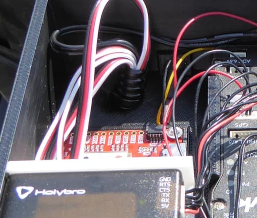
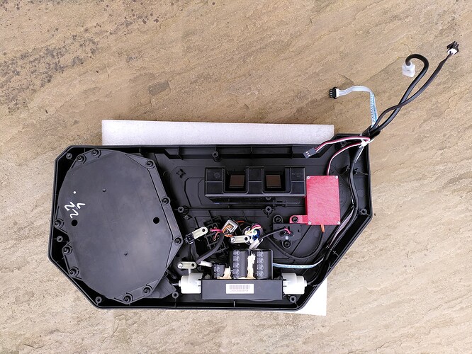
Also, may I kindly ask what the extra cables (black, red, white) are for?

One goes to the ‘signal switch box’…
image

I assume the left switch box is directly connected to the right?!

Leaves three more with question marks.

What about the seat safety switch? Is there some relay or other electronics at work?

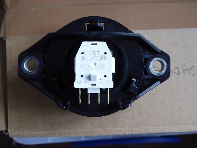
When I disconnected the seat switch, the connector has 3 wires. From what I remember, the seat switch has both normally open and normally closed switches. I was able to get the mower to run by just shorting two of the connectors like the seat switch does. I will have to look at the mower to remind myself of which two wires it was though.

Simulating that behavior by using the Arduino only when the mower is autonomous, and passing through when not, is probably a good idea if I plan on running both manual and auto.

1 Like

The photo you quoted is from when the linear actuators were present, so there’s an extra servo lead for the second actuator.

The other 2 servo leads are for the seat switch and blade control, as you probably guessed.


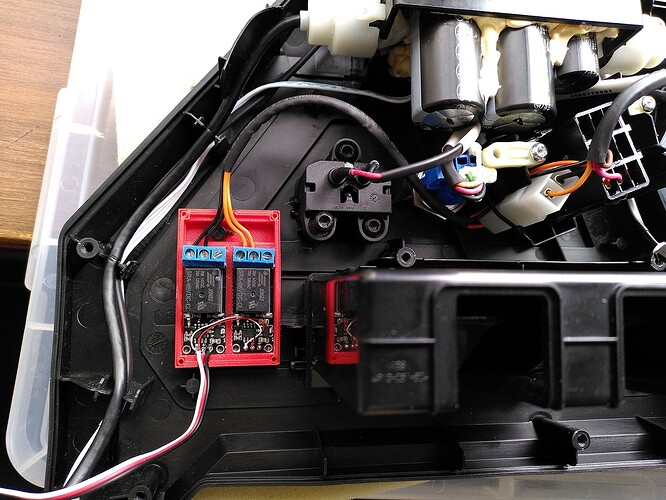
I used RC PWM relay modules to control these because I initially only intended to remote control the mower. If I started again I’d probably just use GPIO outputs.

The seat is just a changeover switch, as Bob suggested, but the blade switch is a bit more complicated. I arranged it so that it can only stop the blade, i.e. the red switch still has to be on for the blade to run, but if it is Ardupilot can then control it.

I’ll see if I can find the notes I made when I did this to see exactly what I did but I didn’t cut any wires so everything is easily reversible.

1 Like

Thanks, I should be able to figure this switch out. I did this on the ZT2, which took me a while until I found the ‘special’ contact, that is opened when removing the connector.

I see :slight_smile: so three cables are in use now:

  1. hall sensors for lap arms (levers)
  2. seat switch, and
  3. blade (engage) switch

I love your work on the switch connectors and cases. Beautiful.
Where did you get the contacts for the seat switch intercepts from?
I still ponder about this seat switch solution; while I would think what connector to use, you ‘simply’ created the connectors to interface with the environment. Awesome thinking.
What I like about these projects and posts, there is always something to learn from.


I do, however, struggle to make sense of the blade speed approach.
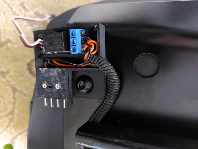
Looking at the image, there are two black and two orange wires… where one orange goes to the white connector. I haven’t dismantled this side of the mower, hence, my question: did you put this white connector in there? There is also the black connector next to the white one (seems to be part of the plastic moulding of the housing.
In essence… I am surprised that:
a) the blade speed wires are outside display assembly
b) the blade speed is not a digital signal going to the motor controllers (located under the seat)

What am I missing?
What are the physical characteristics of the signals (analog|digital)?

I apologise; just went to the mower and realised, this ‘addon’ is for engaging the blades.

I’m not sure where I got the contacts for seat switch from Max. I think they were automotive spade terminals that I had lying around that happened to be the same size as the blades on the seat switch.

Similarly for the blade switch, the black connector is on the back of the switch and the white connector is an automotive connector that I added. I simply moved the orange and black blades from the black connector to the white one. I could then use the blades from the white connector to add new wires to the black one.

The seat wiring is:
normally closed - BLACK and BROWN
normally open - RED and ORANGE
The RED and BLACK wires are connected together somewhere in the bowels of the mower so it functions as a changeover switch.

The blade switch wiring is:
normally open 1 - BLACK and BROWN
normally open 2 - RED and ORANGE
Again, RED and BLACK are connected together somewhere.

I used two single-pole RC relay switches for the blade interface because I couldn’t find a 2-pole version but a double-pole GPIO controlled relay would be a better solution.

1 Like

If you are more resourceful than me you might be able to find the correct mating connector for the seat switch…

The right word for your approach is “elegant”. I like the whole play & play approach, and reuse of existing fasteners.

I haven’t dismantled the right side (display) yet… hence, my initial misreading of the blade business.

Huh, well, I don’t think I will… I was looking for both, connector and plug, when modifying the ZT2, and again yesterday, and could not find anything other than the seat switches.
I have all sorts of spade connectors, hence, will follow your lead.

Having a 3D printer makes things easier. On that note, and if I am not asking for too much, would you be willing to share the STL files for the remaining boxes/cases too?

I have already ordered the PWM relay boards, hence, what I will use. From a spare part and bill of material list perspective, having all relays the same is not a bad idea either.

This is getting exiting… :slight_smile:


On a general note: based on my, albeit, little experience in mower automation, I can only recommend to automate electric mowers, which eliminates the whole servo business, which poses a significant cost, but also a significant complication. The time and money I wasted on automating a petrol mower is something I would not do again.

Just for comparison, a petrol mower requires, if wanting to use it manual and automated:

  1. some form of sensor for the lap arms (levers) on a zero turn
  2. two servos to drive the hydro-stats
  3. one servo to drive the gas
  4. one servo for the choke (if auto start is desired)
  5. two servos to actuate the brakes (is so desired)
  6. modifications to the electrical system, which are less on an electric mower
  7. an upgraded stator to feed the servos with the required current, and prevent the battery from draining.