750$ the batteries set !!! not for hobby use. I read somewhere they use 18650 Panasonic Cell.
10Ah 3s in my 1.6kg wing give a maximum endurance with vertical take off and landing of 37km in 43 minutes.
About your second question I have an other suggestion: to make again accelerometer calibration taking care to enter the exact vertical position you want is hover.
Average 14m/s, seems good but it needs 2x more power than a regular wing. With an FX61 and 3s 5200mAh with 1.6kg, I can fly 45min 36km with no wind. (better in 4s 5.2Ah with wind)
Like the concept of tailsitter (I have difficulties for landing in my country) but if there is high battery drain, it’s better to find a more far open space and take off / land from here. With 2x4S 7500mAh, I can fly a lot more @16m/s than 55minutes.
yes, the tail-sitter cant be as efficient as a plane. This is a challenge but I think I can get 50km in around 1 hour. We will see as soon as the weather gets better. I am also currently working on a small wing made of glass fiber around 20dm² with a much faster airfoil and 2500kv motors. The goal is to make something that fly fast but land easily despite the heavy weight. I just need some courage because I hate to work with composite.
From that one it looks the use 8s3p 18650. But the specs on your link says 97,2 Wh / 14,4 V = 6,75 Ah → equals two cells parallel of 3.4 Ah. Or the cells they use are not up to date on energy density…
Anyways the 1.8 kg cannot be. Cells weigh 45-50g each. 8s3p → max 1.2 kg
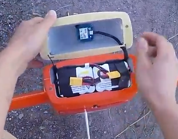
I recently bought six of the NCR18650GA Cells (best energy density I could find) and wired them to an 3s2p. Weight 303g with cables etc. Cells cost about 6-8$ each.
The cells have a MASSIV internal resistance that you better not underestimate: I tested them at realistic test scenario and found out that you can not use them without proper cooling when you discharge them by around 2C. My pack went to 70°C even with a cooling fan on it. (Benchtest) Also the voltage level is way lower then with lipos under same load. On 2C you can calc with nominal voltage of 3.3V/cell. At 2C you’ll only get like around 210 Wh/kg out of them. So conclusion is to only use that kind of cells when you will fly over an hour. (on 1C instead of 2C you’ll only have half the voltage sag, half the current and therefore one third of the power dissipation) Otherwise use Lipos like the Multistar ones.
Background:
I already described how you can tune your PIDs through Ziegler/Nichols method and also did this successful, BUT since we have the PID scaling with throttle in the firmware I can not get my PIDs working as before. This totally screwed up everything and I redid the calculations with new test of the oscilation periods etc but STILL this method is not working anymore
So since weather is geting warmer I was flying and tuning while hovering and ended up using only half of P and I values for Pitch and Yaw from what I calculated them ( I just went for only PI+FF, no D term). My hover throttle is correctly set though. I don’t understand that.
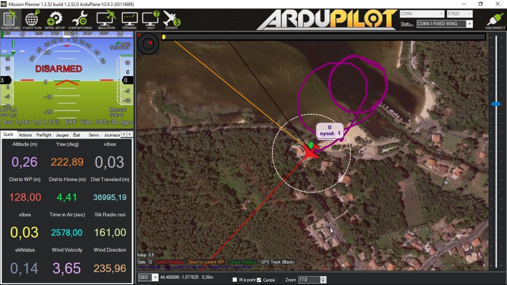
Is there any way to see what PID values are currently used???
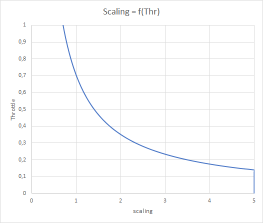
Here you see an example of (what I think) how the scaling code works:
Example hover throttle 70%
Depending on the actual throttle level a scaling of the servo output is applied. The scaling is limited to a factor of 5 and 1/5. (so scaling allowed from 20% to 500%)
When you fly at half throttle needed for hover your servo outputs are being doubled. When you have your throttle at zero, outputs being 5x.
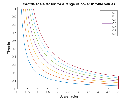
My understanding of the code is the same, I think this scaling of the is responsible for the low throttle D oscillations a few people are seeing. I have plotted your scaling graph for a range of hover thrust values.
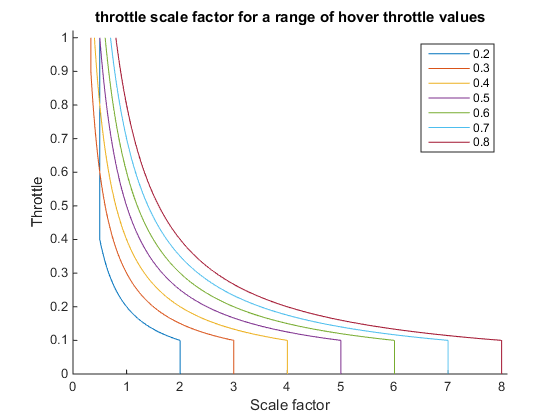
For high power craft with low hover thrust value this causes a very rapid change in scale factor in as the throttle is increased from zero to the hover thrust value. A possible solution would be to scale the maximum scale factor with the hover thrust setting the maximum scale value to 10 * the hover throttle. This results in this graph
This might mess up existing air-frames, so probably a better solution would be to expose the maximum scale factor as a parameter.
As for tuning the best thing seems to be to in flight tuning. Some sort of jig that allows each axis to be tuning independently works well. I think the main benefit of the tuning rigs is just that it stops you from damaging the air-frame if the tune is incorrect. We tried the Ziegler Nichols method initially, using only the P values resulted in a aircraft that would fly but was quite sluggish, the I and D values calculated using time period from the logs were both too high.
So far I have got good tunes using PID’s only with no feed forward, does anyone have any tips for tuning the feed forward? If we’re flying well is there much benefit to using feed forward?
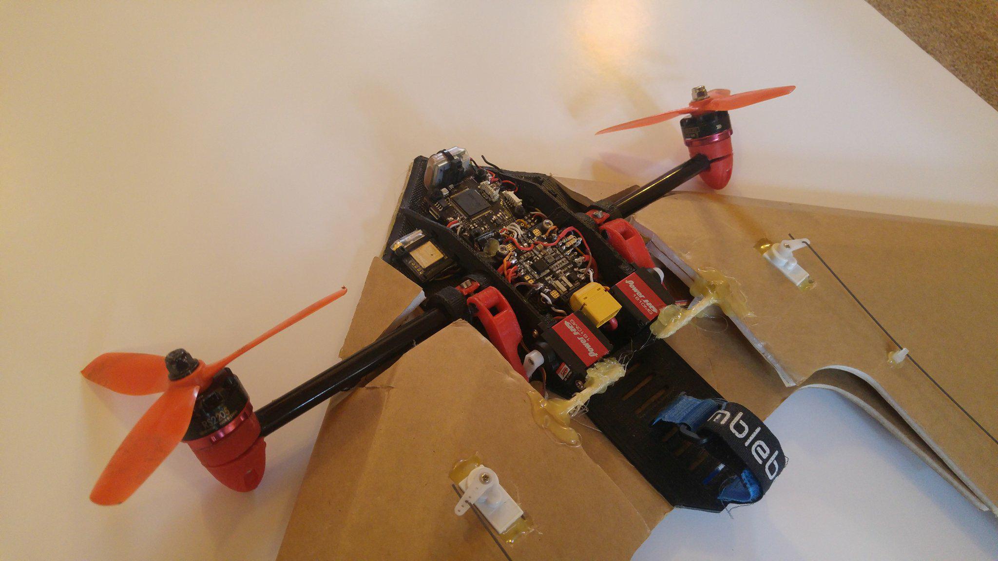
A little teaser, my FT Arrow TVBS (~600g). Flys well in vertical flight mode hope to try forward flight soon.
I’m working on a PR for quad-motor tailsitter support, which involves changes to method QuadPlane::tailsitter_speed_scaling to deal with the need for reducing elevon gains at high airspeeds: https://github.com/ArduPilot/ardupilot/pull/8113
Note that I’ve set the scaling to 1 instead of 5 when throttle is zero.
It assumes that airspeed increases with pitch or roll angle, and linearly ramps down the aileron and elevator controls by a factor of 4 at maximum angle.
That is working pretty well in RF8 at airspeeds up to about 40 mph: https://www.youtube.com/watch?v=dDfmZhdMK2w
The idea of scaling gains with pitch angle is great.
According to my experience, as soon as the wing produce some lift, this is around 40°, control surfaces and motor tilt begin to oscillate. Around 50° these oscillation are not manageable and this is a strong limit to the speed that can be reached when flying Q_hover. The maximum airspeed in Q_hover my wing can reach is around 7m/s and this is not enough to fly safely when there is some wind.
Ideally the scaling factor would be a parameter.
Please keep in mind that RF8 is not doing so well of a job here. EG: My tailsitter which has a symmetrical airfoil NACA00XX flies totally fine in RF8. It glides fine and slowly pitches up when gaining some speed. Only problem is that symmetrical airfoils don’t do that in reality. They are unstable.
Same here. I want to try a more loaded wing, because the speed at which the Tailsitter hovers at a fixed angle depends on the weight of the craft.
More weight → more thrust need to hover → more horizontal thrust component. (And also more airflow over the flaps and therefore more control authority, especially when descending)
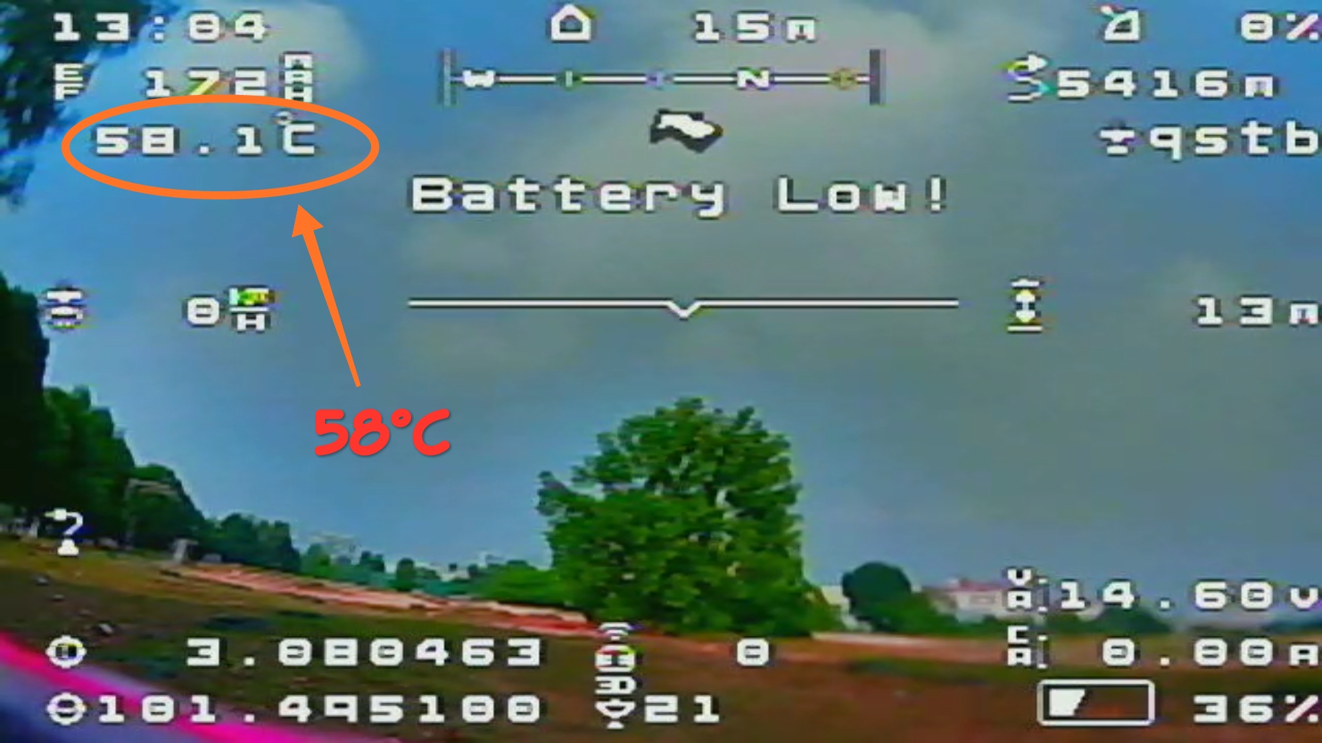
Quick question regarding the max operating temperature of the pixhawk.
In normal flight use (Roughly 10 min) i’m seeing the temperature in my logs reach ~58.1C from a starting temperature of ~30-35. Should this be a concern or is this considered a normal operating temp?