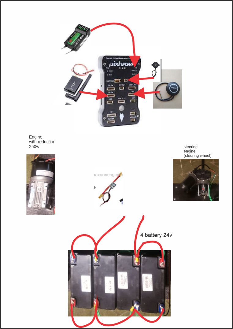
I’m a novice and I’m a little afraid to make the connections for the batteries and the motors on the pixhawk. Can you help me with the right sequence? I am looking to produce an agricultural robot. Sorry for my English.
Hi,
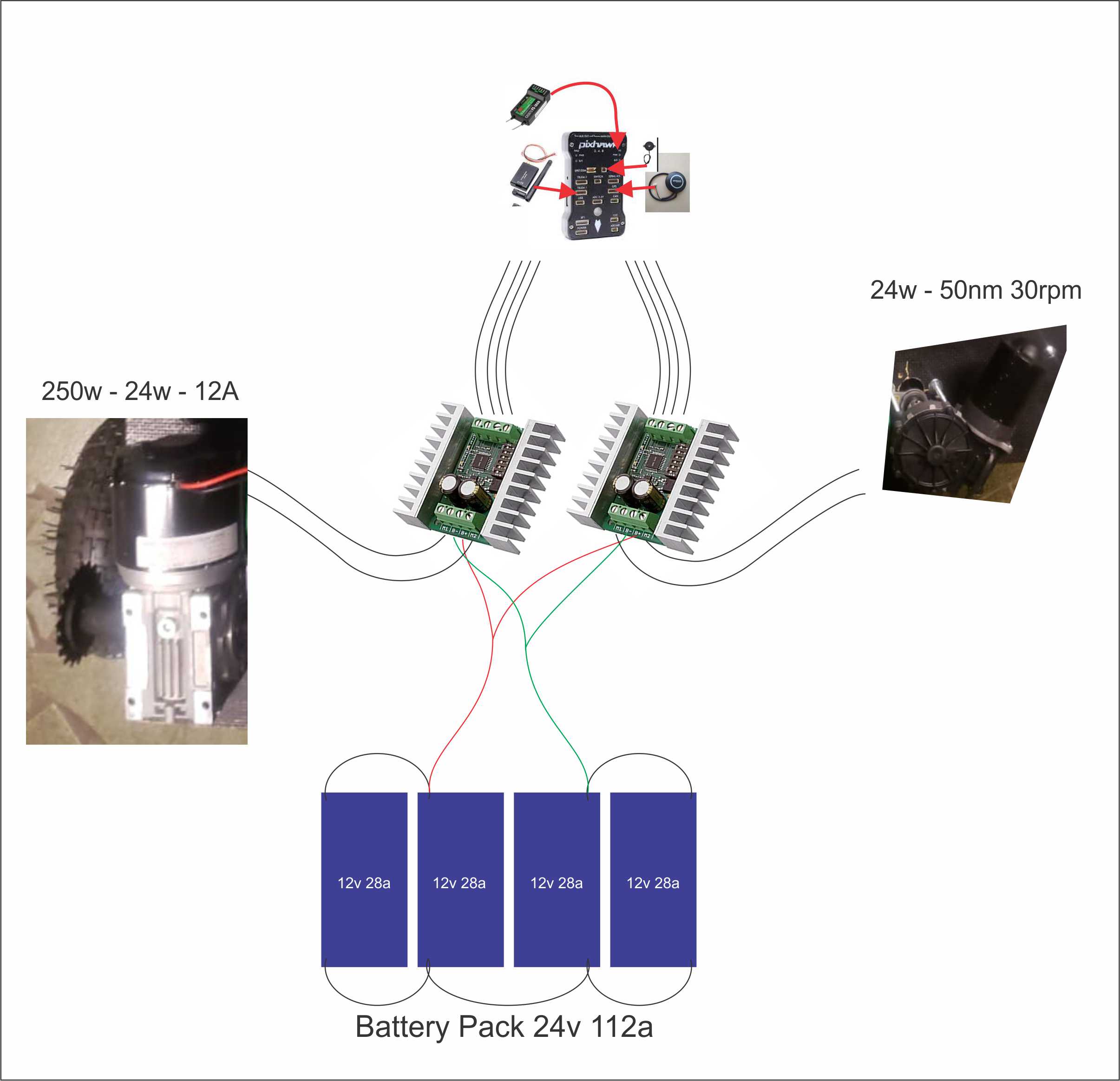
first of all check the voltage rating for your power module. You want to connect 4 12V batteries, 2 in series, 2 in parallel. The nominal voltage then is 24V, but the actual voltage fully charged will be closer to 26V. Most power modules have a rated voltage of 22.2V, so you would go beyond specifications. If your power module has XT60 connectors, solder a matching connector to the wires coming from the batterypack. You need to solder the connector where the plastic goes inside and the contacts go outside:
I do not see any motor controller in your pictures. What motor controller do you have?
I still don’t have the controller, do you have any suggestions?
@Felipe
Sorry, I missed your question. From the picture I guess you are going to use a brushed electric motor. 24V input voltage limits the choice of controllers, because most RC car brushed ESCs support 2-3S (ca. 8,4-12,6V). There are special robot brushed ESCs/motor controllers, like the Roboclaw or Sabertooth series. Most of them are dual motor controllers. They support much higher input voltages and have a lot of other features.
The VESC skateboard ESCs supports both brushless and brushed motors and up to 50V input.
They are open source and are available from different manufacturers. I use Flipsky FSESC 4.12 in two of my rovers with no problems so far.
Roboclaw:
Sabertooth:
https://www.dimensionengineering.com/
VESC:
I’m in Brazil and it’s very difficult to find these pieces here. Does the employee use a 4 relay module?
Ardurover needs proportional control over the motors. On/Off control with a relay will not work.
Would using two of these be a solution? If so, what is the correct place to connect it to pixhawk?

RC car ESCs work well with ardurover if the ESC can be set to forward/reverse mode (often the default is forward/brake/reverse).
But as I wrote before, it will be hard to find a brushed RC car ESC that supports 24V input. Most of them support ca. 8-12V input. Connecting 24V to them will destroy them instantly.
And if you choose to use a relay module to replace the esc controller - it would control the engines, but how would you connect it to the pixhawk?
https://http2.mlstatic.com/D_NQ_NP_668062-MLB45290470499_032021-O.webp
That won’t do anything for you. As was stated you need proportional control. An RC Car/truck ESC with 6S capability would work. They are available but relatively expensive.
In my country it is almost impossible to find these ESCS. But I ended up finding Syren25, I am inclined to use it. It seems that the system is similar to that of Saberbooth.
https://www.dimensionengineering.com/products/syren25
I intend to place 2. One responsible for the traction motor and the other for the servo. Is her pixhawk connection too complex or does it need programming?
The Sabertooth and the Syren are programmed by DIP switches. The connection to the Pixhawk requires two wires, signal and ground.
How does the steering work?
Do you have an encoder for position control on the steering axis?
The project would be getting this way. What do you think? Would you need another direction controller? I thought that now it was just to connect to the pixhawk and configure it on the misison planner.
Ardurover expects a position controlled servo as its steering actuator. A certain PWM value results in a certain servo angle. Your setup means, the PWM values result in different motor speeds. Steering will not work that way.
I stayed with you now. How would the drawing look? what should i buy?
You can use a motor to steer your rover, you just have to add some kind of feedback. I would do it with a potentiometer and an arduino.
Or you have to change the steering actuator to a servo with enough torque.
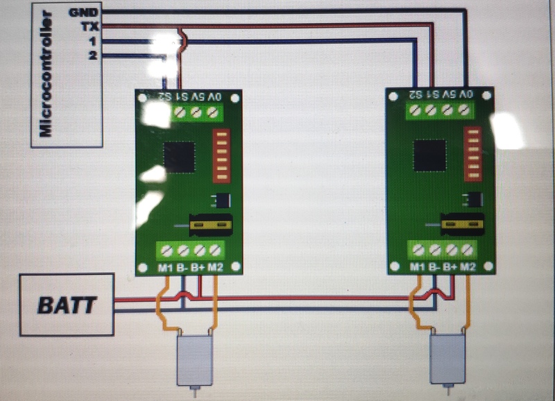
I was thinking of doing something in this direction. I just don’t know what the pixhawk connections would be like
The Syren controller is connected via S1 and GND to the Pixhawk. You have to set the Syren to microcontroller PWM input mode via DIP switches.
But that will only work for propulsion, steering still needs some kind of feedback/position control loop.
I have no idea how to do this. Do you have any suggestion?
As I wrote above, I would use a potentiometer and an arduino to turn the steering motor into a big servo. If this is easy or hard to do depends on the mechanical layout of the rover/steering mechanism. The arduino reads the PWM output of the Pixhawk (setpoint) and the output of the potentiometer (process variable) and a PID controller generates the control signal for the Syren/steering motor. This is what the electronics in a servo do.
If you are refering to the DIP switch setup of the Syren controller, Dimension Engineering has a link to a DIP switch wizard on the product page of each controller. It asks you questions about what you need the controller to do and presents the correct DIP switch settings at the end.