DATAD 2.4Ghz telemetry link 2+W open source

Hi!

We are finally ready to release this telemetry board.

After months of testing and design changes we have finally arrived at a final design, integrating a very flexible and capable board to provide customization for every project.

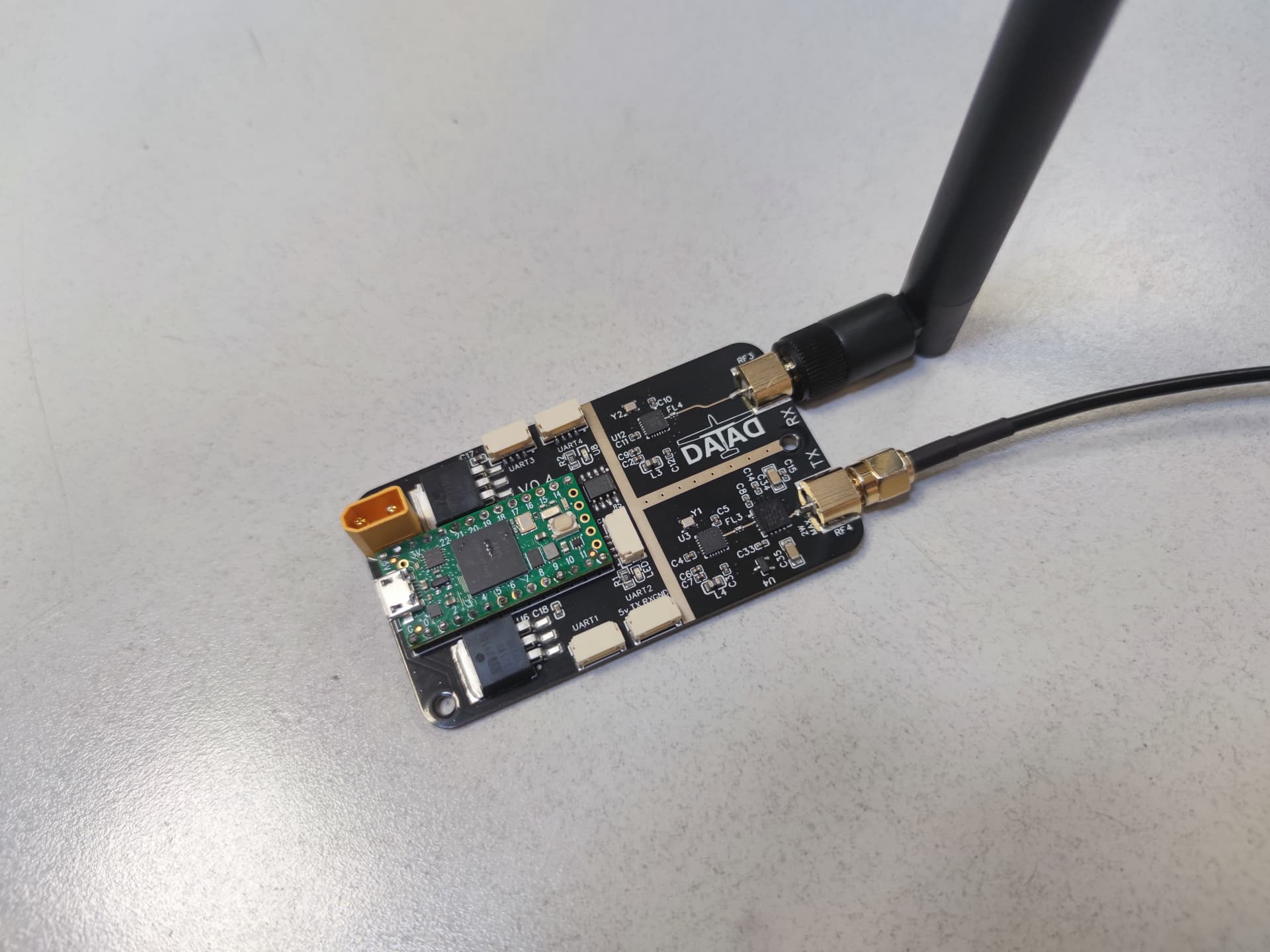
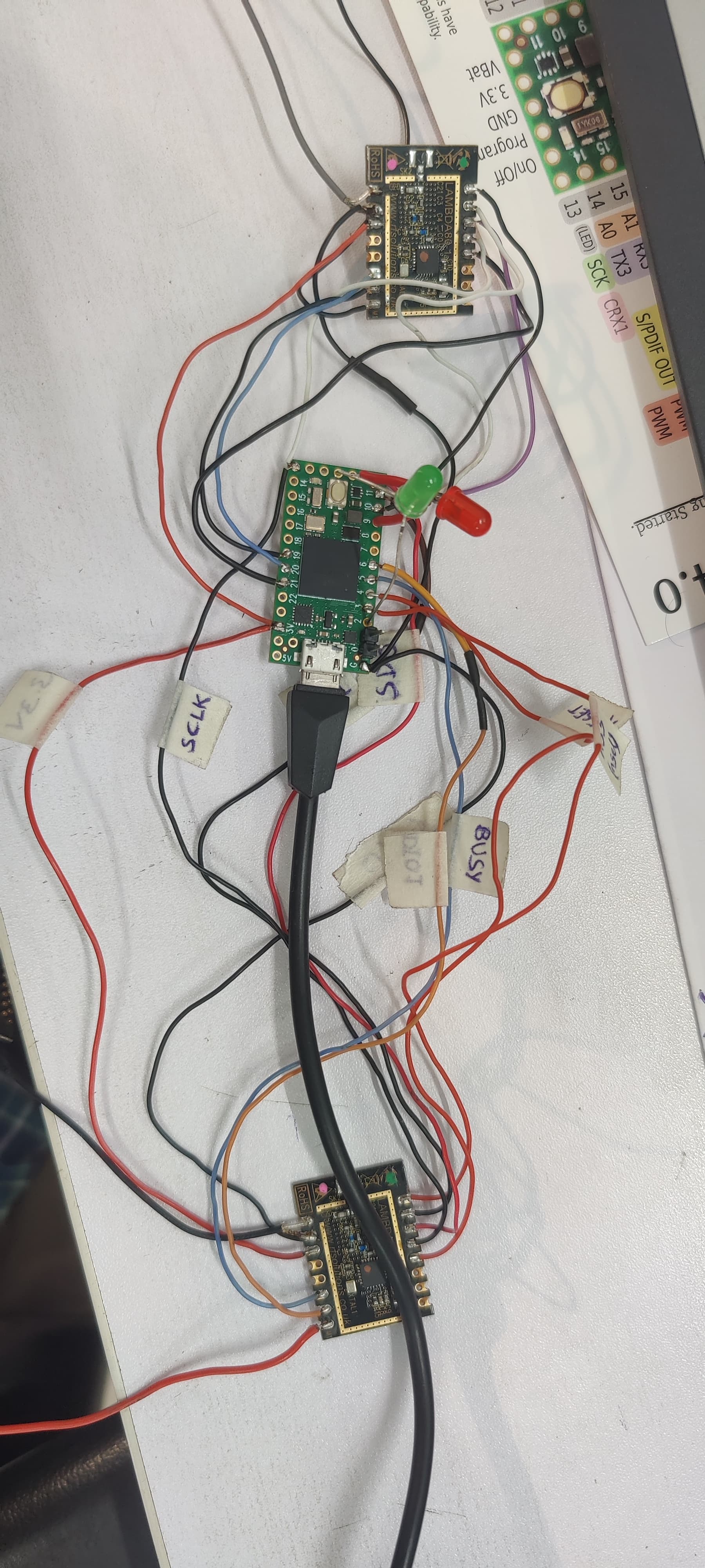
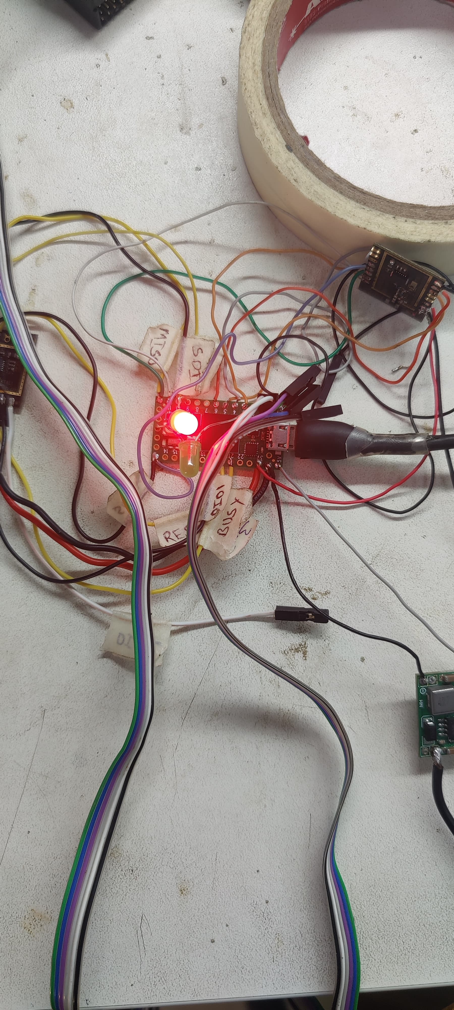
The main core is the teensy 4.0 with various exposed pins in the 4 pin jst connectors, all of them are serial capable, some have PWM and there is a CAN-BUS IC for the integration in any project.
To power the board can be provided by: a XT30 connector to accept 6-26V power, USB from the teensy, or from the jst connectors(5v). For high output power is preferable to use USB or the XT30 connector and a heat-sink)

The main feature of the board is the twin SX1280 working together to provide real full duplex communication on two different channels. The output power on TX channel is from 16 dB up to 34 dB, the other channel used for RX is capable of transmitting but is normally used for continuous reception.
The speeds are using the example FLRC modulation is 325k with 3/4crc → 240 kbps of effective data rate with a -106dB sensitivity in reception. The band can go up to 1,3Mbps, with -96 sens.
If the LORA modem is used in the maximum sensitivity options -132 db can be possible to transmit for hundreds of kilometers (theoretically).

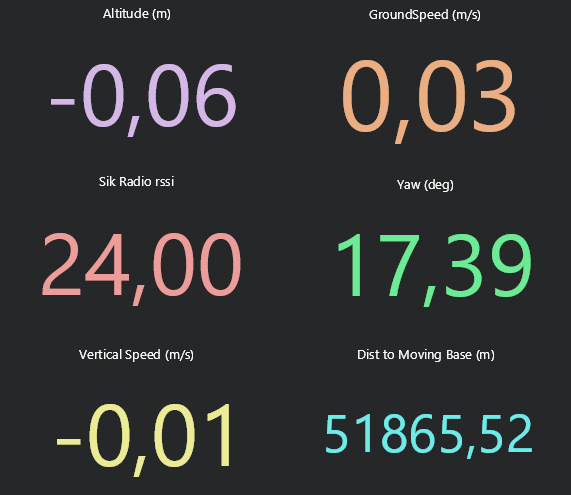
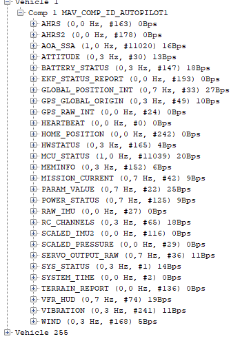
The standard program on Github provides a communication link from USB ground station and a UART on a vehicle, on the ground the telemetry is mirrored to the UART1 to link an AAT.

The testing at 30 dBi showed good results, at 1300kbps with a 2.5dBi mimo antenna on either side of the communication, we achieved a link distance of 6km, but with a 18 dBi panel antenna and a aat we easily achieved 15km with a tree line in the way and a very stable link.
For the maximum range the RX and TX antenna should be as far as possible, especially at full power ( if the antennas are close more than 30cm you can burn the reciver)
You can have a general idea of the range for your setup with this simple tool:
https://www.immersionrc.com/rf-calculators/

The staring price of the board is 150€, without teensy 4.0 and heat-sink.

We will provide a simple manual and a more refined standard program later, obviously you can modify the program to do other functions, like a normal arduino.

The program is on this git page:
https://github.com/Xarin94/DATAD-telemetry-2.4Ghz

The physical dimensions are 45x80mm and 30 gr. with the teensy.

5 Likes

Today I did the first long-range test!

The transmitting end was on my house roof antenna with an omni antenna 5dbi.
The receiving end was a 15dBi antenna, a flat panel one, handheld while I was looking at the PC.
The data rate was at 650kbps and the transmit power was at 30dBi, the refresh rate on the board was set to 1 Hz to avoid draining the small battery in the 6 hr I was away.

I was on a mountain but a mountain top was in the fresnel zone and some trees were in the way, so not optimal conditions.

The result is beyond my expectations, with the correct orientation I received everything at -90dBi, so 12 more to use.

Immagine 2023-09-16 124301

Considering this result with a 24dBi antenna we will try to follow a 150km plane flight, to push the telemetry to the limits.

Side note: I had tried the classic 5dBi antenna on the receiving end, but the received signal was sporadic, maybe 40 km with a 5dBi-5dBi setup is the actual feasible limit.

2 Likes

Added: support to read RC controls from PPM and send direct RC link to the air unit with Mavlink encapsulation or PPM output (sbus in/out is in development). The read/ send rate is customizable it supports 50Hz with no problem, the uplink channel is independent, so the RC link will not interfere with the Mavlink downstream even at high loads.

Hi,
we are facing a problem with the module,
when we try to connect the arducopter using mission planner, the datalink hangs and teensy module restarts, please help

Hi,
Can you post a photo of your setup? you are using only my firmware, seems a power supply problem

i tried with external power supply 5v also
the below image shows the hanged module while trying to connect in mission planner


w

The sx1280 mus be used with 3.3v, the teensy output of 3.3v is 500ma capable, but it should not be used to provide power to the radio modules. i use a LDO from 5v(usb) to 3.3.
The rebooting of the teensy is caused by a drop in tension.
The leds have a resistor? if not it is a short circuit…

1 Like

tried with 3.3v external voltage also,
leds are without resistor, but without leds also it was not happening, when autopilot starts transmitting more data while connecting, the problem is happening, first it will hang as the image above, then teensy will reboot

try this:
-Set the same tx and rx frequency;
-Delete the part of code with the RADIO_STATUS output, so you do not have to use mavlink library.
-Write some text on the arduino serial monitor, the text should be sent back to the monitor without any modification, if this does not happen the modules (or only one is bad).

is there schematic pdf? so that i can check the connections in my prototype?

The pinout is in the firmware itself, but your connections seems ok.
I will not provide the schematic of connection, otherwise i would have a public pcb project

Okay,
thanks a lot for your time