Hello,
I noticed that when connecting, for example, a camera switcher via PWM to the AUX OUT servo rail, the device does not work. However, when I connect it to the MAIN OUT rail, the PWM signal is read, and I am able to switch between cameras.
Could this be a software issue?
What else do you have configured on the AUX outputs? Are you mixing output protocols within a timer group? There are 2 timer groups on AUX outputs on Cube Orange+
Just found the solution, just set the right one: “BRD_SAFETY_MASK: Outputs which ignore the safety switch state”.
The solution of setting the correct BRD_SAFETY_MASK value turned out to be ineffective. The same problem still occurs, when I connect the cam switcher to the pins from the AUX OUT bus, the cam switcher doesn’t work. On the MAIN OUT bus, the cam switcher works without a problem. In the MAIN OUT bus, I have signals from six ESC, so the pin number 7 and 8 is not used.

You need to answer Dave’s original question. Most likely, you are attempting to use AUX pins for both DSHOT and GPIO, and depending on exactly which pins are in use, you may be attempting to run incompatible signals on the same timer group.
I don’t know what the parameters responsible for assigning the appropriate protocol timer group to the AUX OUT and MAIN OUT outputs are called, which I should check.
No. You need to answer the question. What hardware is connected to which pins?

AUX OUT:
1 - power input servo rail (5V),
2 - N/A (here I would like to connect cam switcher, but it isn’t working)
3 - N/A
4 - N/A
5 - N/A
6 - power output (5V)
MAIN OUT:
1 - motor
2 - motor
3 - motor
4 - motor
5 - motor
6 - motor
7 - cam switcher (it’s working here)
8 - N/A
OK, so what related settings do you have now (with the switcher on Main Out 7) ?
And what settings have you tried when you move the switcher to an Aux output ?
On the radio, channel 6 is set to the camera switch.
In Mission Planner, I simply have:
SERVO7_FUNCTION; 65 (RCIN6) - with this setting I am able to switch between cameras, when I change to:
SERVO10_FUNCTION; 65 (RCIN6) and plug the plug into the AUX OUT servo bus with number 2, the cam switcher stops working.
I tried all the ports in AUX OUT and different settings of the BRD_SAFETY_MASK parameter, but nothing worked.
I managed to get a working cam switcher on the AUX OUT bus. By disconnecting and connecting the plugs to different sockets at some stage I connected the receiver incorrectly, which is why the channels on the radio were not read. Thank you for your interest!
I would like to refresh the topic, because I noticed a certain dependency that directly affects the operation of the RCIN6 channel, to which I connected the Cam switcher.
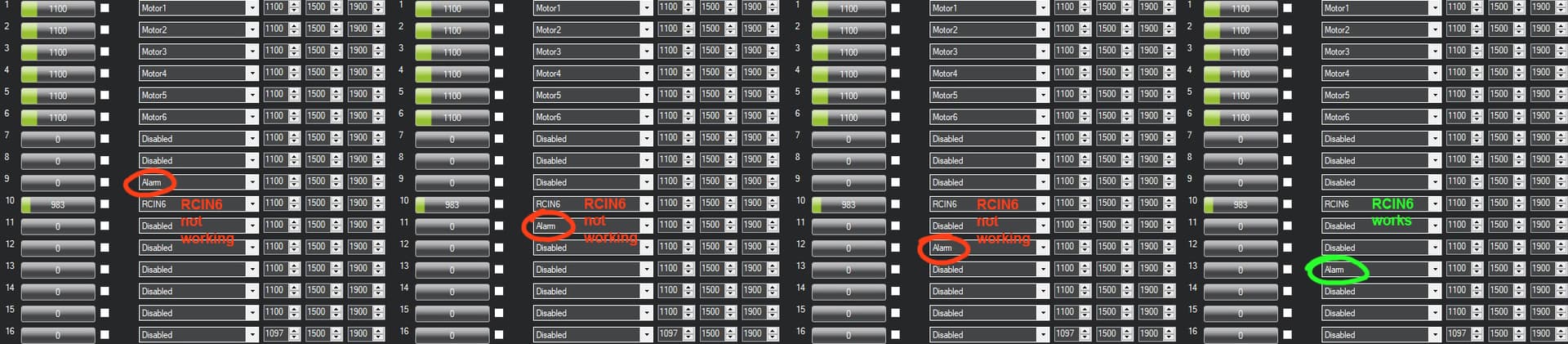
I want to connect an active buzzer to the AUX OUT servo line. The operation of the RCIN6 channel for some reason depends on the distance from the servox_function; Alarm - as in the diagram below.
What could be the cause of this?
This has to do with how the AUX OUTs are grouped in terms of protocols. You can’t mix protocols within the same group. I believe AUX1-AUX4 are grouped and AUX5-6 are grouped for the Cube Orange. So you can’t put the buzzer and camera switcher in the same group (only one will work).
1 Like