HI! I have a problem with the battery monitor on my V5+. When the vehicle is on the ground, the calculated voltage is correct, but when arming and exceeding 20% throttle, the calculated voltage does not mark the correct voltage, it is 0.4 to 0.7v below the correct voltage.
Here are my settings:
Monitor: Analog Voltage and Current
Sensor: 8:CUAV HV PM
Ver AMP: 0: CUAV V5/Pixhawk 4 or APM1
Yes, I had the same issue. I believe it’s a design fault with the HV PM. I raised this with CUAV but they didn’t conduct any simple tests I asked for (or at least didn’t tell me the result) and wouldn’t admit it’s a design fault.
If you’re only using 3 cell then 0.6 or 0.7 is a significant voltage drop, or error in the measurement!
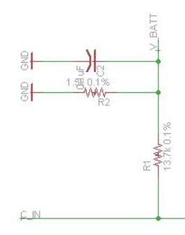
I added my own voltage divider circuit, 2 resistors and a small capacitor, to the battery input side before the current sense resistor (shunt) and joined it to the voltage sense wire that goes to the flight controller. I cut the voltage sense wire, leaving a small length from the HV PM connector in case I ever wished to use that output again.
You can use the same resistor values and layout as the original 3DR pixhawk voltage divider, or choose your own value resistors to suit your battery voltage range. The vsense input to the flight controllers has a maximum input of 3.3 volts.
R1=13.7k, R2=1.5k, C2=0.1uF In this pic “C_IN” is the battery B+ input, and “V_BATT” is the scaled voltage sense wire to the flight controller. It’s important to use metal film 1% resistors.
With my custom voltage divider, I’m using BATT_VOLT_MULT,5.644802
The current measurement setting is BATT_AMP_PERVLT,25.68 derived from bench testing and flights
I’m not sure what you mean.
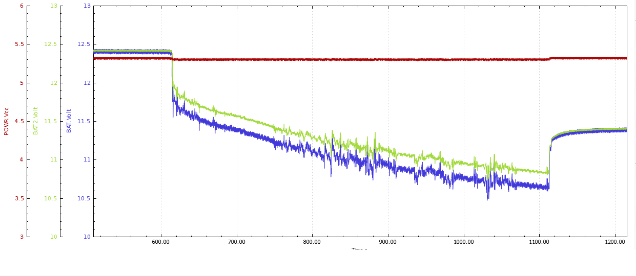
But anyway, here’s a graph I did at the time showing the CUAV HV PM battery voltage output (blue) versus the output from the custom voltage divider (green)
You can see the voltages are almost identical when at rest, and the green trace is the true battery voltage under load. I had the custom voltage divider connected to the secondary Power input so both could be logged at the same time.
Now we have the custom voltage divider “wired in” so it’s output goes to the standard power port on the flight controller, along with the +5 and current sense from the HV PM, and I’ve supplied the amps per volt value that I use.
Hi @xfacta. I assembled the circuit using the same components you indicated and got a good result, now my V5 + is measuring the battery voltage correctly.