Hey All,
I recently had an octorotor fall out of the sky after an entire day of successful flights.
If you can glean anything from the logs that would lead to the problem I would appreciate it.
I also appreciate any and all questions.
Thanks,
Hey All,
I recently had an octorotor fall out of the sky after an entire day of successful flights.
If you can glean anything from the logs that would lead to the problem I would appreciate it.
I also appreciate any and all questions.
Thanks,
I see a 6s setup, you let it go as low as 21.2v , what is you land-voltage ?
(that question is in no way related to the crash)
The log ends midair, most likely, the flight controller lost power, I see no warning signs in VCC graph.
Did you provide redundant power to the flight controller (at least two different +5v sources ?) - and , is it a properly made one, or maybe one of those bad clones that cut cost on power selector ?
It is a 6S setup. We had low voltage set for 20 volts and to land immediately, kind of pushing it but nothing dangerously low.
The pixhawk was a Pixhawk 1, made by mRo. I am very confident in the components used. We did not provide redundant power but that will be standard on all aircraft now after this incident.
Thanks for taking a look.
yes, “provide redundant power within correct voltages” is the best conclusion in this case.
Could you please elaborate on this suggestion? Do you mean that we should provide at least two other +5V sources from the same battery, or to be truly redundant, should we have at least two other battery sources on board?
How do the “bad clones” cut cost on the power selector? And how do we identify if we have one of the bad clones? Can the power selector be tested on the ground?
My apologies for all the questions, but this topic is of interest to me as I had a solder joint at the battery connector fail, which could have been disastrous if it happened while flying. And in this case, redundant power sources from the one battery to the FC would not help.
We never push our batteries to 20v - that leaves very little, if any, margin. After observing two drones fall out of the sky due to poor battery management, we RTL at 21.5v. I used to think that was way too conservative. I no longer think so.
I said at least two sources, 2x 5v regulators, you may as well feed them from the main battery, as the battery pack should have very high MTBF when considering power loss, and an total power failure in the battery pack will bring it down anyway.
To have logging in case an battery pack soldering/interconnect fails, you can add a supercapacitor to one/both of the 5v sources, so that AP will continue for a while after a power loss…
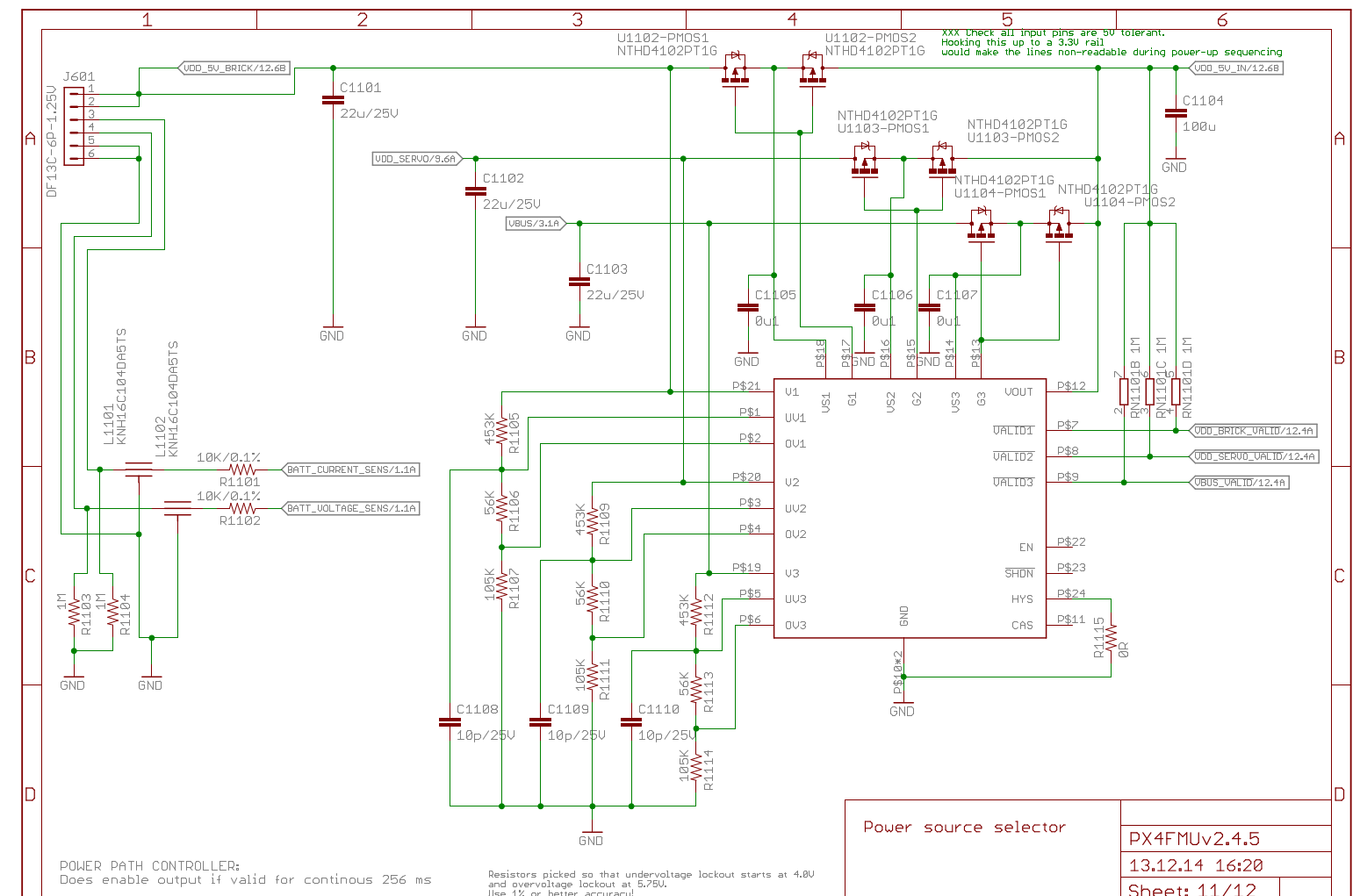
Bad clones omit the IO buffers , power selector IC, omit or use smaller capacitors, etc, theres a lot of components to save by omitting the prioritizing, sophisticated, power selector of an proper Pixhawk.
all this:
if in doubt , you can compare the electronics you have inside your pixhawk with a proper one, or post good photos of both it’s PCB’s sides.
Sorry, you did too … ![]()
Thanks for your detailed reply - it is very informative. Where did you source the circuit diagram from as I would like to see the schematics for the other sections of the FC, too.
I am not sure that I follow why it is important to duplicate the 5V source to the FC, as I would not expect the 5V regulators to be any less reliable than the power selector in the FC or the connectors (plugs and sockets) in the power supply chain to the FC? I agree that duplicating the 5V supply removes a potential single point of failure, but there are still several others in that 5V path?
5V Voltage regulators may provide power to other, less critical systems, like servos, gimbals, retreats, onboard computers, payload - one would rather not have an issue with those, bring down the voltage below 4.3v or make the regulator overshoot to >5.6V (in case of bad regulator)
Beside the other 5v devices, the 5v switch-mode regulators itself, having heavier components like inductors and heavier capacitors, are at a little higher risk than other electronics to fail due to vibrations, than small, light components on the autopilot.