Derek,
Personally I would not mess with the ATC_ACCEL_X_MAX. Leave those at the 110000. Those limit accelerations regardless of the input size. The feel really comes from ATC_INPUT_TC in the stabilize and althold modes. This will limit accelerations based on the input size. I have found that ATC_INPUT_TC value of 0.2 to 0.25 to be very nice for flying. I just tuned up a Trex 700 and have 0.22 on it. As for angle P, I don’t generally recommend lowering that. I would use autotune to see where you are at with the rate loops. I found with my 700 that it had a lightly damped pitch axis which required some special filtering to reduce the overshoots. If you are not looking for a super fast heli and just want it to fly nice in stabilize, I have a recommendation for the filtering that would help. I also would not recommend change expo until you have adjusted the INPUT_TC.
@bnsgeyer Bill, that would be nice to go over the filtering. I do have some very fast servos, which should reduce damping in the roll and pitch axes, I would think. I am using Promodeler DS490BLHV servos with 2S LiPo. Specs show a speed of 0.078 sec/60deg at 8.4V. Torque is 490oz-in at 8.4V. They are very quick when using RC passthrough to move them.
I did have a question about the RPM sensor input. There is spiking in the RPM reading occurring soon after reaching 1400RMP. Perhaps I am surpassing the sample rate capability of the flight controller? Seems like that would cause a 1/2 cut in RPM reading rather than a spike, unless the flight controller is attempting some kind of compensation. I am using the HobbyWing 260A RPM feedback. This is a buffered feedback with a 3.3V high state square wave. The motor is 10-pole and the drive gear to pinion ratio is 104/9. This gave me an RPM1_SCALING factor of 0.008653846, however, RPM was being reported at half its actually speed, so I changed this to 0.017307692.
Not sure what rate ArduPilot can accept RPM signal input, but that is my first thought as a potential reason for this spiking.
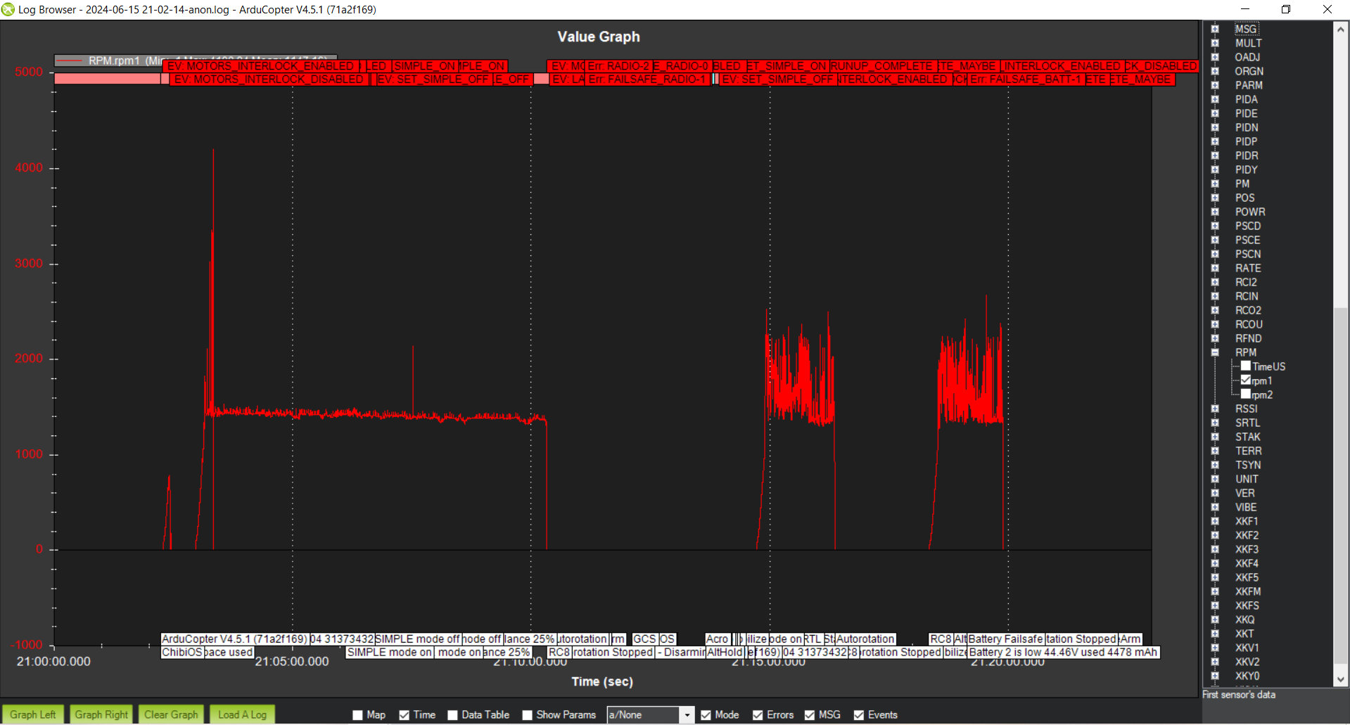
See log 2024-06-15 21-02-14-anon.log in shared drive.
I’m trying out the auto missions. Just did a RTL test, which was supper cool! It came right back and landed itself so beautifully!
When planning an auto mission, if my mouse hovers over the home location, it shows Alt: 230. I guess this is my takeoff altitude, even though I don’t have a takeoff command set? I would like to reduce the takeoff altitude, but am not finding the option to change it anywhere. where can I adjust the takeoff altitude? Or maybe I need to be explicitly providing a Takeoff command?
You need to provide a takeoff command and altitude in the mission. The 230 might be your altitude in reference to Mean Sea Level?
Takeoff will be your first command in the mission planning, you can specify the altitude it will climb at before moving to the next waypoint.
I would suggest to play and experiment this stuff with SITL, it’s super useful and you can explore pretty much everything related to mission planning!
That’s the altitude provided by the GPS, so it’s AMSL.
I’ve been running the simulator and then doing some auto missions with my helicopter! It’s been great! Made a few Photogrammetry maps on DroneDeploy.
I started trying to set the camera gimbal angle from the mission plan using DO_MOUNT_CONTROL. It seems that this command is causing the copter itself to move. It is moving far off course during a 2-second DELAY command immediately after the DO_MOUNT_CONTROL command. I’m looking into why this is. I have read that this command will control the YAW motion of the helicopter if the gimble does not support yaw, but it doesn’t make sense that pitch and roll might also be affected.
. . .
Okay, I was experiencing this issue: Heli drifts on Auto takeoff with AC 3.6.0 - #6 by bnsgeyer
I had my WP_NAVALT_MIN set to 5 meter. I figured this would prevent movement at low altitudes. It’s doing just the opposite. I guess I’ll set it back to 0.
Yeah, I think I set mine at 0.5 or something small anyway.
I guess you already know this WebODM Drone Software - OpenDroneMap™
I came across WebODM recently, but haven’t stopped to research that option just yet. Haven’t seen this link though. Looks like it does everything! Thanks for pointing me to that!
DroneDeploy doesn’t seem to offer any real control or accuracy for survey grade design.
I was trying out AgiSoft. Its a bit of a learning curve, but models seem to be quite accurate.
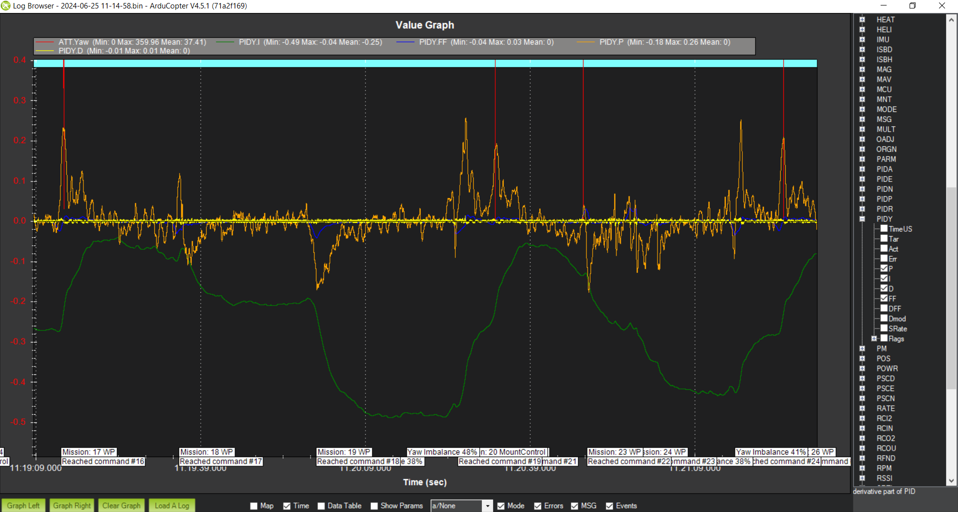
My Yaw I scaler is maxing out in the wind. I figured I increase my ATC_RAT_YAW_IMAX from 0.33 to 0.50 or so. And maybe increase the decay rate of the I-leak. Not sure where that parameter is though. Would this be the correct way to handle this, or are there other parameters for dealing with wind specifically?
. . .
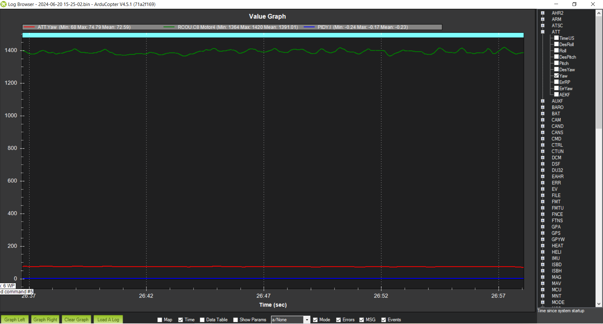
Or, maybe I need to increase my I-term. The tail trim is set to 1400 PWM. The I-term is still pretty low even when hovering near 1400 PWM for the tail servo.
. . .
The I-term is negative whether the PWM output is above or below 1400, which is a little confusing to me. I guess it is leaking off slowly though. This tells me that the I-term should be increased to increase the rate of change for error correction.
Flight Log is uploaded as 2024-06-20 15-25-02-anon in the shared folder
. . .
Also, a related concern is with fast spool-up when bailing out of auto-rotate. How would I tune parameters to provide a fast tail response for fast spool-up? Seems I would need to clear out the I-term, and have a larger D-Term in the moment.
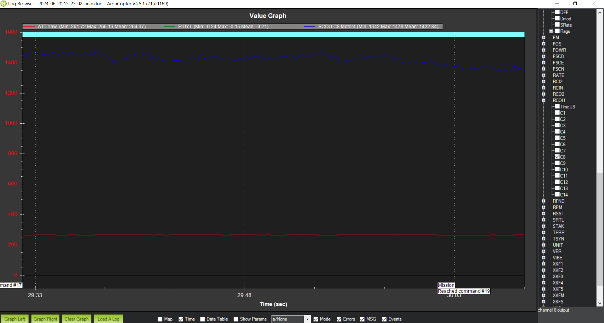
I increased ATC_RAT_YAW_IMAX from 0.33 to 0.5. but left the ATC_RAT_YAW_I where it was at 0.12.
This helped avoid Integrator I saturation. Looks like I should increase IMAX still, probably to 0.8.
Now, I’m unsure if ATC_RAT_YAW_I gain should also increase, or possibly decrease. My thought is that if it is increased, that means more authority to correct actual yaw error, with less change over time required, meaning that less time is required for the correction to be made. Is this assumption correct? That a higher I-gain will be quicker to respond to change?
ATC_RAT_YAW_IMAX at 0.33
ATC_RAT_YAW_IMAX = 0.5
. . .
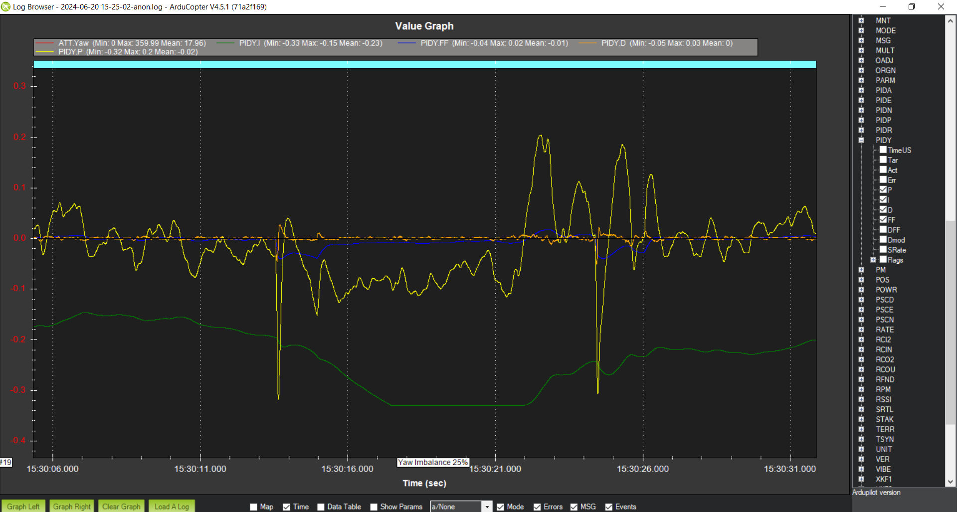
I’ve doubled the I-gain from 0.12 to 0.24. The yaw has a little overshoot now, and some twitchiness. Seeing some oscillations in the P-gain, so P-gain should be reduced.
Also having a hard time understanding why the I-gain is offset relatively far, even when the tail PWM output is very near the PWM trim value. I guess I’ll set the trim higher. 1420 is the overall average PWM. I am in some wind, but this offset has been consistent.

I-offset
Hi Derek,
Instead of guessing with manual tuning, why not use the autotune feature. I would set the gains back to what you originally found in manual tuning. You can do the FF gain tuning but that typically can be set to zero. The rate P and d tuning sequence can accurately set these gains according to the desired max gain parameter. I think you should start with AUTOTUNE_GN_MAX of 1.0. Then have it set the angle p gain with the AUTOTUNE_GN_MAX set to 1.4. As far as the I gain, I have it set it to 10% of the Rate P gain. You can make that higher but I think the rule of thumb on that is not to exceed the rate P gain.
After you complete the tuning of the yaw axis, perform a tune check sequence so we can see how it looks.
What accel do you have on yaw rate right now?
Okay, I’ll go ahead and learn the autotune feature. I would like to verify how to calculate the max gains for myself before going through this procedure. That is, I would like to find out what my current maximum gains are. Do I simply add P, I, D and FF rate gains together? For me, after manual tune, that is currently
P + I + D + FF (0.28 + 0.12 + 0.003 + 0.028 = 0.431) for Yaw. Do I really want a max gain of 1.0 for yaw?
ATC_ACCEL_Y_MAX = 80000
That’s not how it works. The autotune max gain refers to the response gain which is the output (angular rate) divided by the input (requested rate). The autotune feature looks at the response gain across specified range of input frequencies. The desire for a good tune is to have the output match the input up to as high a frequency as possible. When you start seeing overshoots in the response, that is indicating that the output to input is not 1 to 1.
Look over the autotune wiki and come back with any questions.
Okay, I just did an autotune for the tail Rate-D and Rate-P gains. It failed, maybe due to the wind. I’ll try again. What determines a failure? I gave it plenty of time to tune, but it decided that it had failed during the tuning process.
as for the I-gain offset I was seeing earlier, that was due to my H_COL2YAW = 1.0. I ended up setting this back to zero for best results.
Tail Rate-D and Rate-P gain log is found here
There should have been a message. But I will look. You should try to only use autotune in low winds for best results.
It exceeded the max frequency when trying to find the max allowable gains. So you should raise the AUTOTUNE_FRQ_MAX to 100. Then try it again.
I completed Auto Tune for the Yaw Rate-P ad Rate-D gains. It seemed to remain in the dwell state for a long time. I had to interrupt to bring the helicopter back. After the interruption, it did not return to tuning. Looking at the data, it appears that it was actually finished tuning. The final P-gain is 0.5! which is much higher than your recommended P-gain value during manual tuning. The yaw feel is nice though. Could it be that this heli, having a tri-blade main rotor, and only a two-blade tail would require a higher gain than a typical two-blade rotor heli?
See the Rate-P and Rate-D tune log
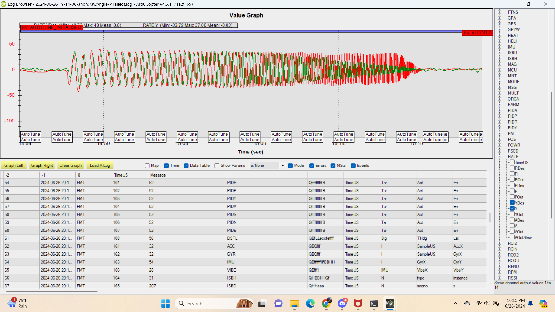
The angle-P tune failed. Looking at the data, it appears that I need to begin with a lower frequency. That the gain only decreased from the beginning.
Angle-P autotune log (failed)
Yeah, I have seen it able to tune to higher than expected gains in the yaw axis. I got the recommended value for manual tuning from a previous heli dev from his experience. I didn’t have much experience with yaw tuning. I rely mainly on the frequency response to tell me when its getting close to instability. There could be other considerations like actuator workload where it is being driven pretty hard.
So this is the frequency sweep done during the angle p tuning which includes all of the rate p and d tuning. The desired and actual rates are about equal in magnitude at the lower frequencies.
So the error with the autotune of angle P was due to a frequency exceedence again however this was due to the min frequency not being low enough. I would suggest the following for the min and max frequency for angle p testing
AUTOTUNE_FRQ_MIN 2
AUTOTUNE_FRQ_MAX 50
Run the angle p test again. It is looking for the maximum response gain and then dwells at that frequency while it raises the angle P gain. It stops when the response gain exceeds the AUTOTUNE_GN_MAX parameter.