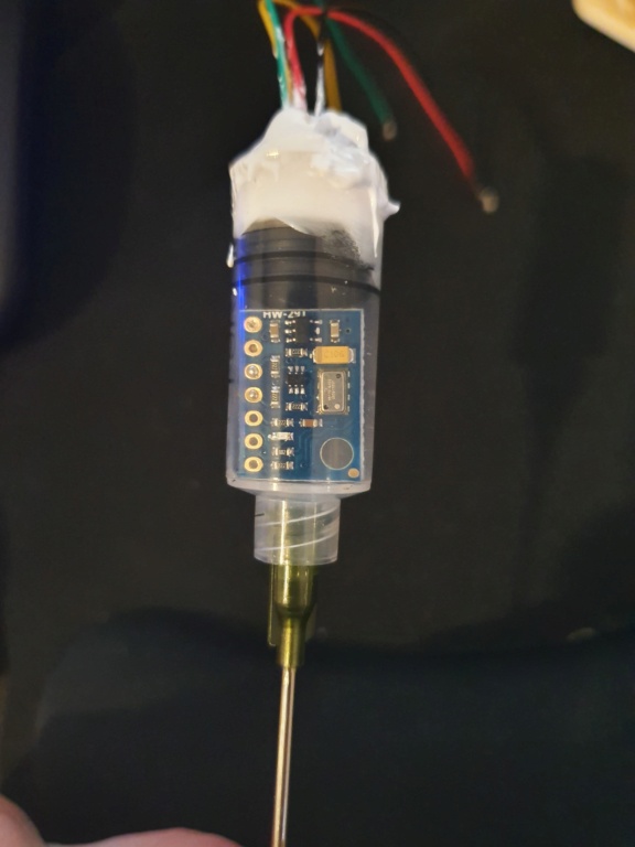
I have enclosed an i2c MS5611 and have it working with inav for testing depth. If it goes well then it might be worth a test with arduplane. I havent had a chance to test my tug with its pitot tube as the ponds have been iced over.
2 Likes
Greetings to all submariners. Now it’s my turn to puzzle over the issue of integrating ms5837 into my submarine. Tell me how you solved the issue with choosing the firmware? Which one did you choose: ardurower or arduplane? Our boats are very similar, the tasks and associated difficulties are also similar. floating models are quite flawed in ardupilot.
I have been looking at the issue of adding sensors to ardupilot and Inav without having to make custom ardupilot firmware to make everything match up so after looking at all the options MSP makes the most sense as its got Barometric pressure, rangefinder and airspeed over a single link so it should be relatively easy to make a converter tailored to submarine sensors that reads my MS5611 barometer, GL041MT serial sonar and water speed sensor, scales it then sends that over MSP, It should be compatible with both Ardupilot and Inav.
I have a rough draft of a esp32 converter done that compiles but I’m struggling to find any examples of Arduino generating MSP sensor data so I’m not sure if it’s correct and all I can find is other people asking the same question and one example on how to read it. I haven’t had a chance to test it yet.
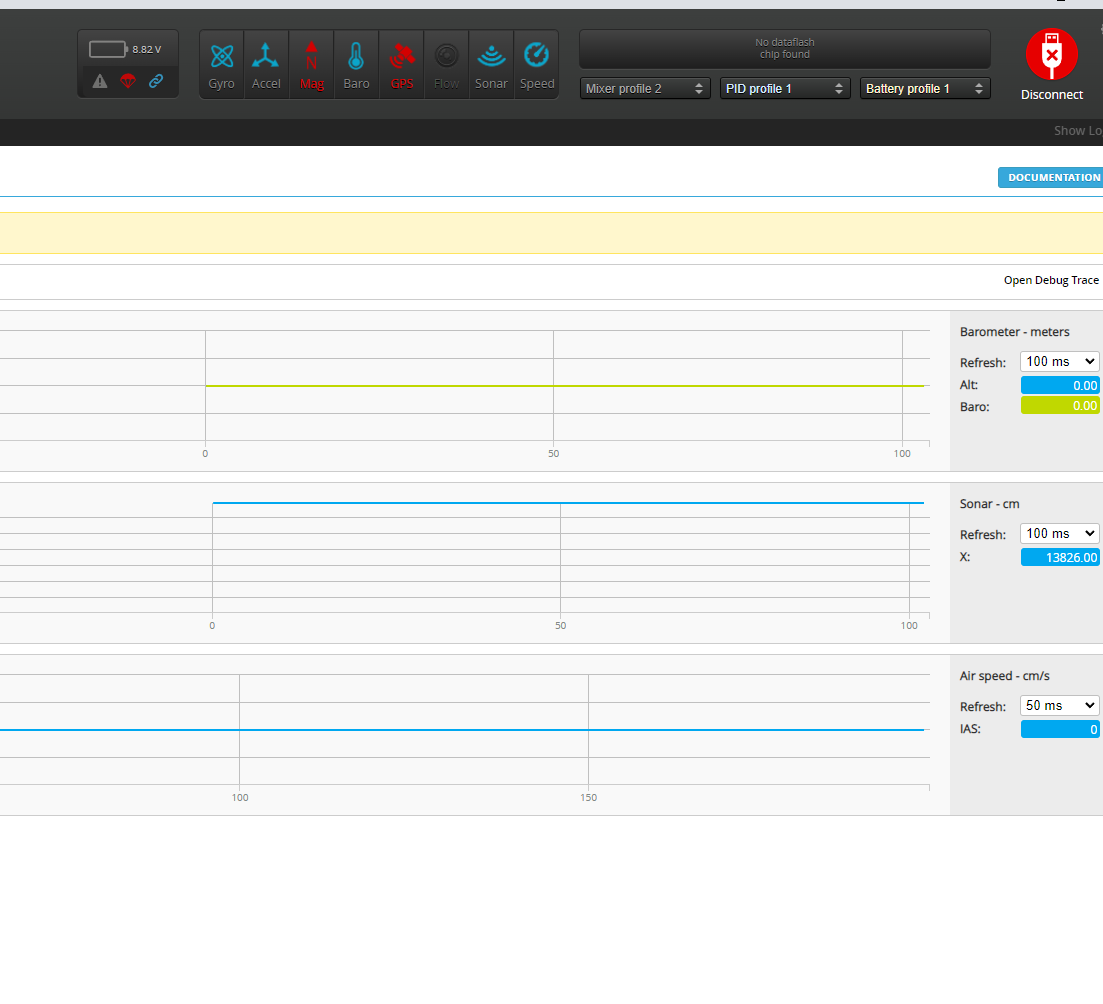
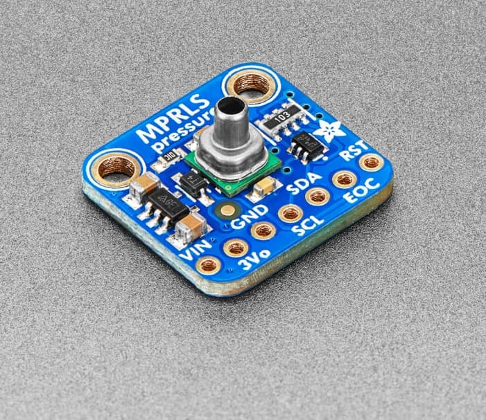
Some initial testing using Inav shows the MSP interface is working and I already have the sonar working. So now it’s just the barmetric sensor and speed sensor to integrate. I have ordered this Adafruit MPRLS Ported Pressure Sensor Breakout to replace my glued MS561. its designed for relatively high pressure so it shouldn’t have any issues on RC submarines.
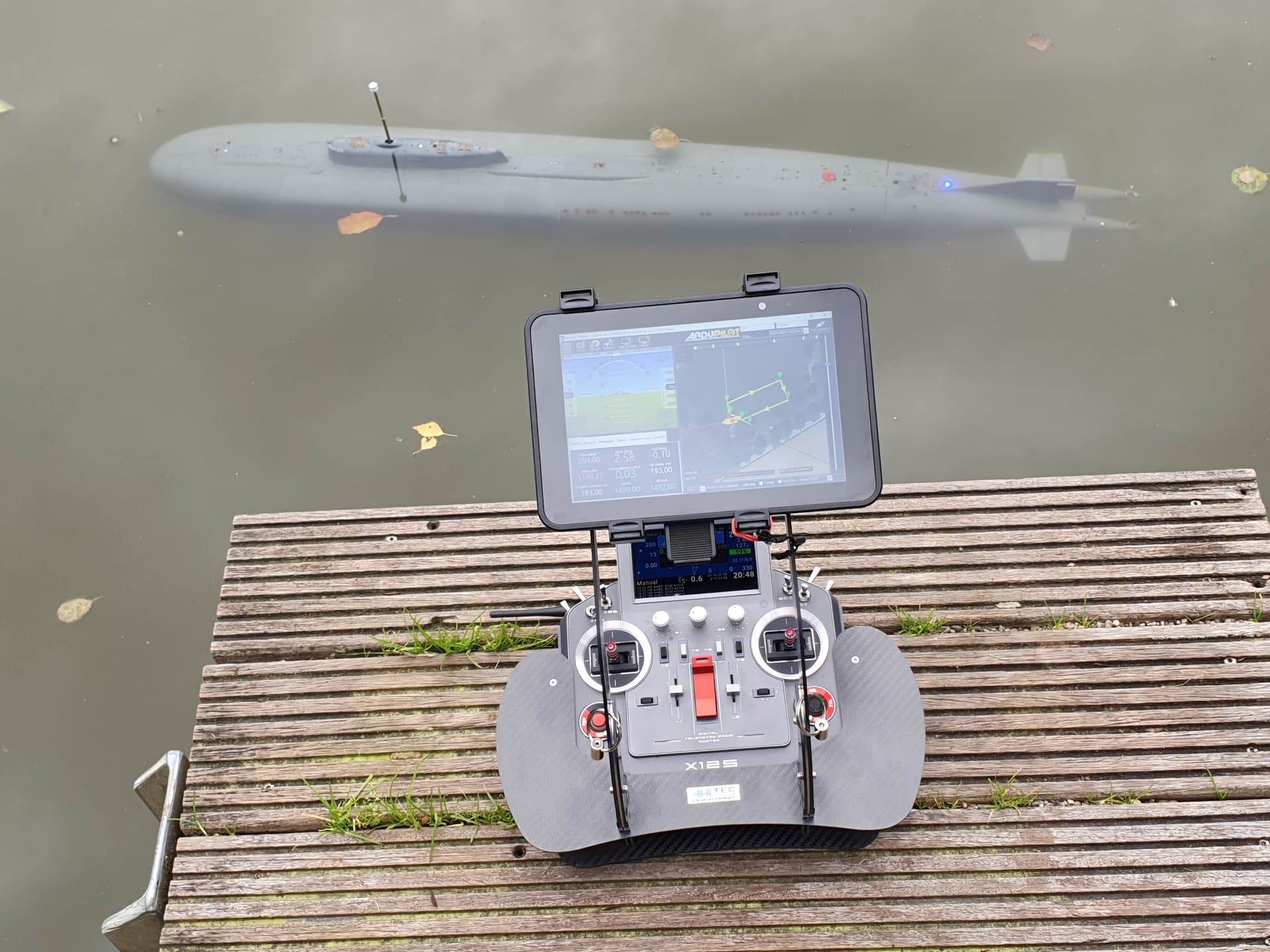
I had my submarine out a few weeks ago and it basically sank again for the second time, it lost control as soon as it went under and kept driving until it hit the side of the pond. it was almost an exact repeat of last year when the same thing happened, but because the first time around there was a leak and water in the hull I just assumed it was that causing the problems this time it was dry. turns out the Radiomaster R900 receiver i was using is junk, the failsafe doesnt work at all, it just holds the last input, even set to custom or no pulse so when it was loosing signal it wasnt stopping like it should have, it just kept going until it hit the side and popped up again where i regained control. Something I didnt take into acount is the proximity of the pond to the sea. its a freshwater pond filled with rain but due to occasional flooding and spray from the sea I think there is a lot of salt in the water and that’s why I was loosing signal only a few cm under the water less than 20m away, as bad as the R900 was it should have been able to do that in fresh water.

I have ordered a new receiver, it’s 500mw running mLRS on it, I don’t plan on running it at 500mw, I suspect it would overheat above 100mw in an enclosed tube, but I wanted the extra for testing.
I’m going to test the water salt content next time I’m at the pond to make sure it’s not a mini dead sea, my tugboat already has an esp32 for sensors so im going to add a EC sensor to it for measuring the water conductivity so I can get an idea of the salt content before the sub goes in. it would be easy enough to integrate with ardupilot as you could just send the value as a named float. you wouldn’t even need a esp32 as its just an analogue sensor, you could connect it directly to a ADC on ardupilot and read it with lua. or just set it up as a voltage gauge where volts = ec.
https://www.aliexpress.com/item/1005001698342637.html?src=google,
a little handheld one would work fine too I just like to make it complicated lol
I have been trying to get everything connected to the flight controller but the omnibus f4 pro board I am using just doesn’t have enough outputs. I thought 5 would be enough but with a motor, rudder, forward planes, rear planes and now a dive pump and trim pump it just wasnt enough, and now im not using a receiver with servo outputs I cant connect anything directly to it and I also wanted to add some other stuff so it was becoming a problem.
I have replaced it with a Speedybee F405 mini Wing controller, it’s got 13 servo outputs powered by an internal 4A BEC and native support for Express LRS style receivers that use a UART rather than an inverted SBUS input, All of that is going to make wiring much simpler.
Another benefit is that it has a built-in camera switcher so I could have 2 cameras connected and switch between them. So one on the periscope and one on the sail.
Another things im looking at is telemetry over audio, in theory this library should work but I’m not sure if its going to be fast enough to do anything useful, something like the high latency packet might be ideal for it. It also has a 140 character limit per message so some mavlink packets will need split to work.
I have been thinking some more about what this could be used for, and the best idea i have is for a moving baseline position system. Essentially if we have 2 sonar transducers with some separation as a baseline then a pinger on the sub to respond, the baseline sends a ping that tells the sub to respond with a ping exactly a set time after its received, the difference in the time the ping arrives at both baseline transducers could give you direction and the response time will give you range, so if you know the position of the baseline you can work out the position of the sub and send that back via the sonar data link.
Most of it already exists so it would only take some small modifications to make it a transponder system.
1 Like
Hi Geofrancis - thanks for sharing the up´s and down´s in getting your sub running. The video is neat. Couple of issues sound all to familiar to me. Back in 2022 I switched from “good old 40 MHz radio” to 868 MHz (FRsky Horus X12S / RFD TXmodem 868 MHz / RFD 868 x modem). I got my sub running stable @ 868 MHz - TX and MAVlink telemetry range more than sufficient - above and under the surface. BTW you really need a working RC failsafe. Unless you enjoy these very particular moments when the sub suddenly gets out of sight - before running into something - or you pull all levers to surface…
1 Like
The failsafe was set on the receiver, it just doesn’t work and it’s not the only radio master receiver I have found with this behaviour, the 2.4ghz R88 radio master receiver I have does the same thing where it ignores all failsafe settings. its been replaced with a 500mw ELRS recevier running mLRS, I have this on all my other vehicles, the only reason the sub was still on R9 was it was running inav, and I thought it would have been good enough since I wasn’t going to be going more than 30cm deep. The plan is to eventually move it to ardupilot but inav is much simpler to test sensors with. Because the sensors are going over MSP, once they are working it should just be a matter of flashing it to get it running ardupilot as it fully supports MSP sensors.
yes - that occured to me as well - but I solved it - let me know whether you are interested in switching your RC gear to FRsky - the Horus X12 is sold out - but you could get one at Ebay or elsewhere - same for the ZEBRA tab I´m using - only the RFD items arent available 2nd hand - and unfortunately come with a c
ertain price tag.
I have a Horus X12s and a X9E, I use the Horus for my aircraft and the X9E for my surface vehicles as it has a lot of switches. I dont expect any more issues once its changed over to ELRS/mLRS.
what are you using for depth control? Ideally I want to get ardupilot to control its altitude, my current idea is to set it up as a VTOL plane with the ballast tanks setup as lift motors so it will fly through the water dynamic diving as a plane then transition to static diving using the ballast tank with the trim tank for pitch control.
great - you have one already - I´m using separate controllers for static buoyancy and dynamic depth and pitch control. Bow and stern dive tanks adjust only (static) bouyancy. Depth and pitch are controlled dynamically by deflection of the stern mounted dive planes adjusted to desired diving depth by a depth and pitch controller (LTR5) available at http://www.modelluboot.de and connected to an AP PWM output. The TMax2 is designed for “old style 40 MHz” radios and requires 3 separate PWM outputs to drive 2 separate piston type dive tanks - 1 bow / #2 stern - ch1: tank empty/tank partially flooded for neutral buoyany/tank full // ch2: trim bouyancy // ch3: trim pitch. The TMax2 exspects sequential PWM signals on ch 1 to 3. Because the AP servo rail transmitts all PWM signals simultaneously I placed an arduino nano between AP and dive tank controller to convert the simultaneous input to a sequential PWM output signal - the script is here https://rcarduino.blogspot.com. Perhaps most importantly the TMax2 blows the balast tanks if rc signal is lost.
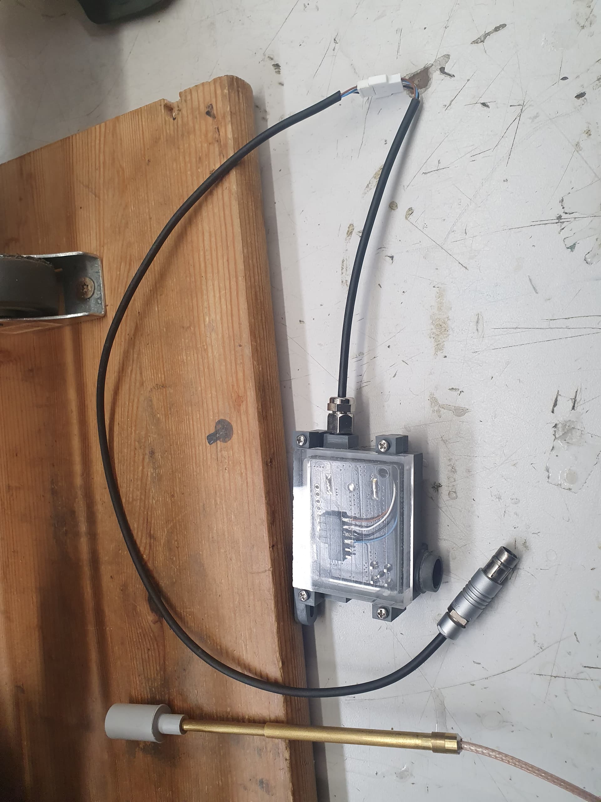
I took an old servo, removed the board from it, replaced the potentiometer with an analogue pressure sensor and the servo motor with a peristaltic pump connected via a motor driver and I had an automatic depth control system, it worked but it would over correct if you tried to change its depth too fast.
If i cant get the flight controller to do depth control i will probably do a similar approach but using arduino and a PID loop.

1 Like
what a smart system for static depth controll - wish I had space left within the pressure hull for an additional small volume static dive tank… 20 ml would suffice… With increasing speed dynamic forces via stern mounted dive planes become the dominant factor for depth and pitch control - how did you manage pitch control for your sub?
p.s. is there any particular reason for the cloverleaf antenna?
it’s set up as an aircraft so its just using plane pitch control to keep it level when moving but it has a small second tank at the stern for pitch trim, I have that on a switch so I can select between manual control, following the pitch or auto levelling.
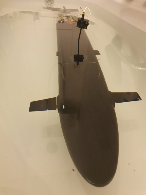
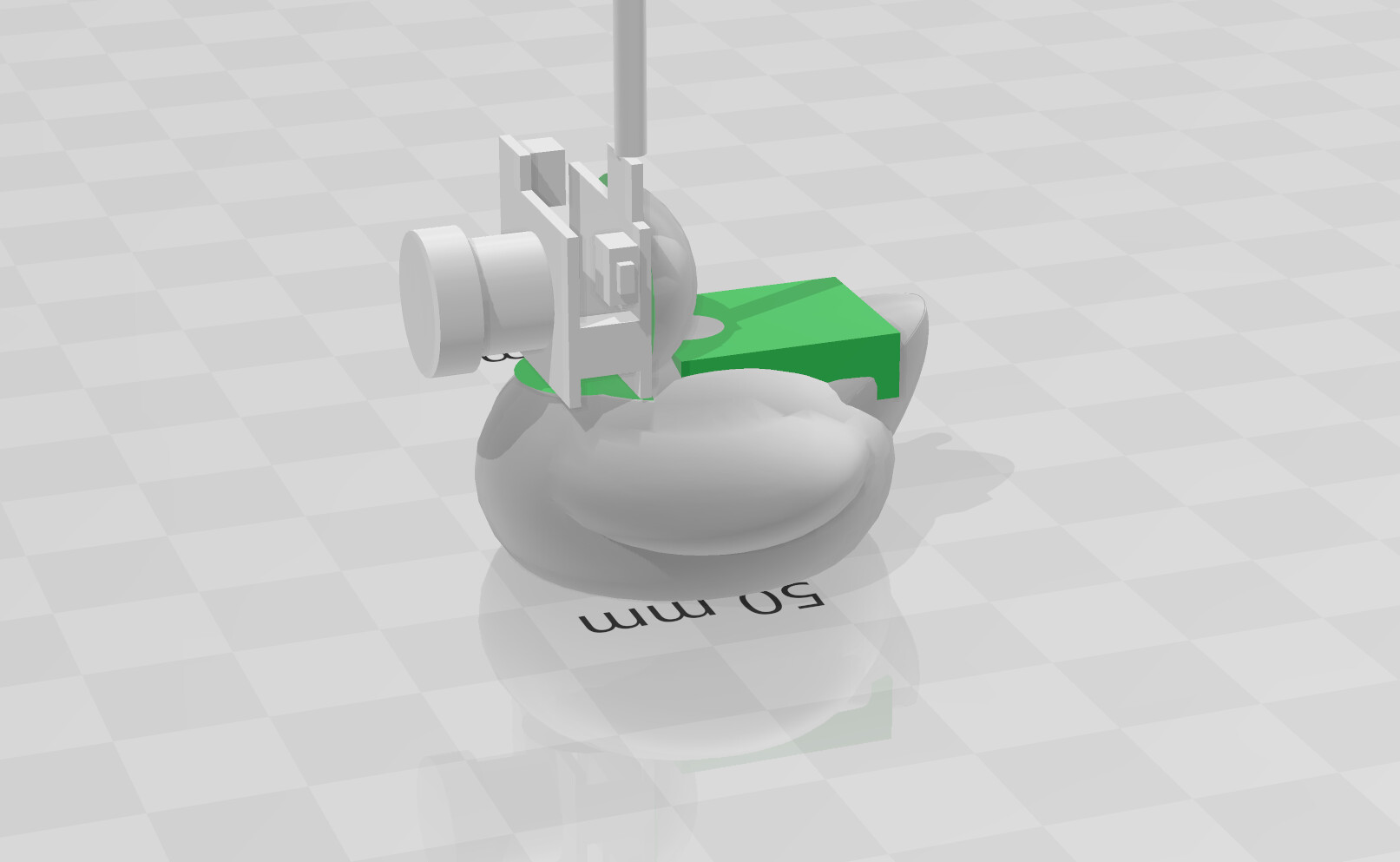
The cloverleaf is on a little 25mw AIO FPV camera that i use as the periscope. It’s got a clover because it was just the only spare camera I had sitting around at the time. The idea is that it will run just under the surface using its depth control and I can FPV it by keeping the camera above the surface. I just sealed it with epoxy to make it water proof, It gets around the problem of trying to get a video signal through water. I will probably mount the GPS antenna to the mast too.
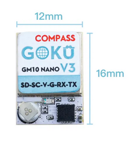
I was going to put a tiny GPS and compass behind the camera and seal it with epoxy. this is probably smaller than I need, I could go a little bigger for a better signal.
I also thought about making it an aircraft (or blimp) initially.
Needed to made some corrections on the previous post on depth and pitch control.
Please update on your periscope GPS once its tested.
1 Like
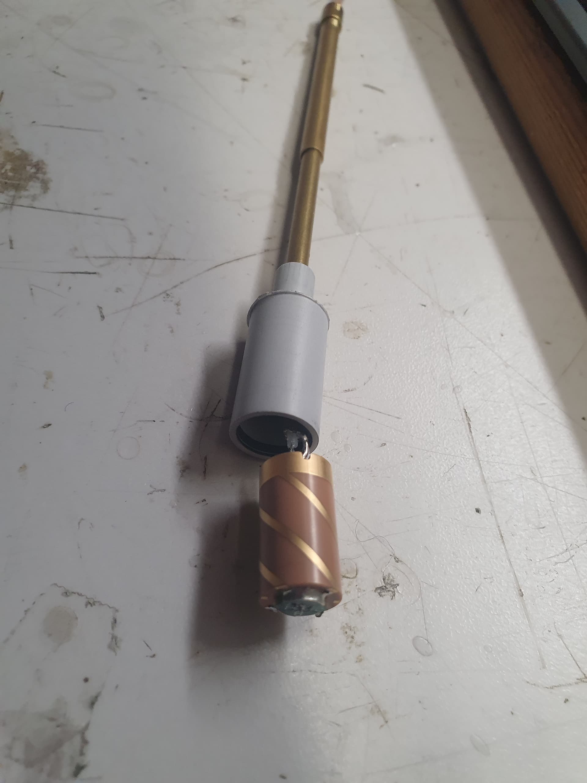
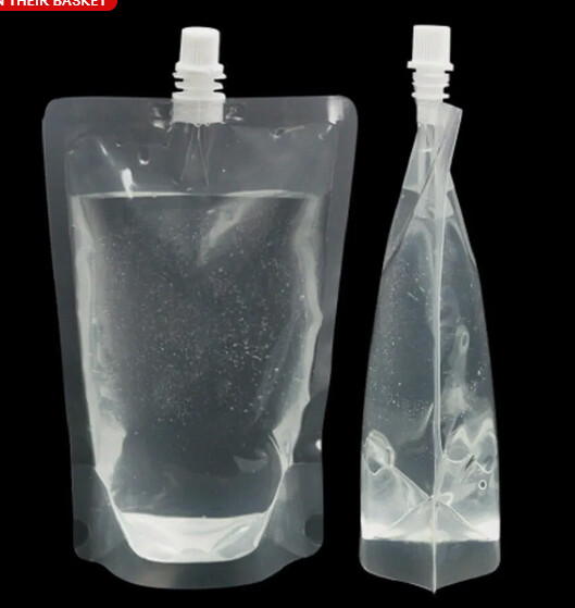
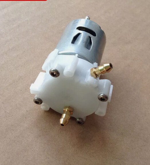
I should clarify, i dont use actual “tanks” on my sub, its got drink pouches that i use as water bladders, there is a large 500ml one in the center with a small 100ml bladder and the end of the WTC, the large one is driven by a geared pump as its fast and the trim pump is ran with a small peristaltic pump
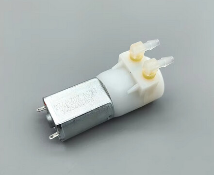
https://www.aliexpress.com/item/1005005336619812.html
I use one of these for the trim pump and run it from the servo bec
https://www.aliexpress.com/item/1005007168797907.html
I was looking at some kind of hydrodynamic cover for the gps and camera but I think this is a better idea lol It should look better once its smoothed and painted yellow.
1 Like
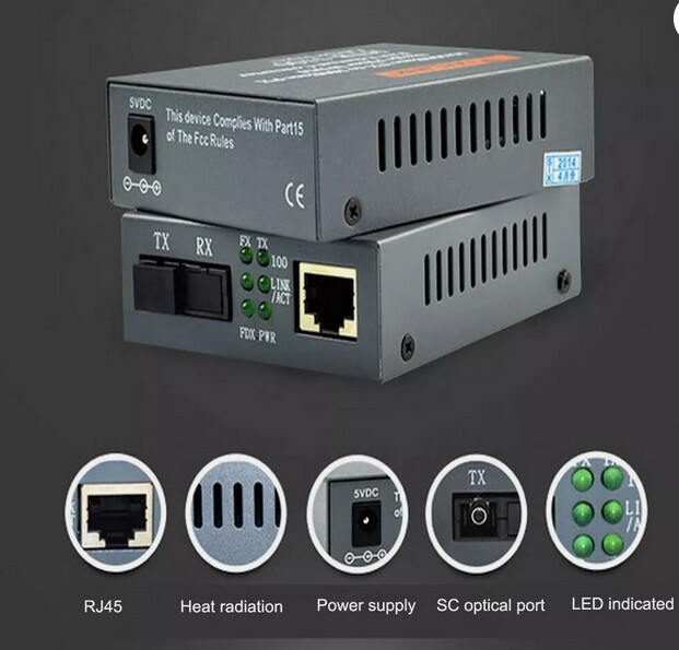
I was sent this,

They are using light to get digital video from the sub, I have been thinking about how they are doing it and I think it might be possible to use one of these old ethernet to fibre adapters with the little led that would normally light up the fibre replaced with much larger LEDs and a lens on the receiver, as long as video being sent over UDP then it should work as a one way system.
I have ordered a bunch of these waterproof sonar transducers, im going to embed a few around the sub so it doesnt crash into anything.
https://www.aliexpress.com/item/1005002504451529.html?
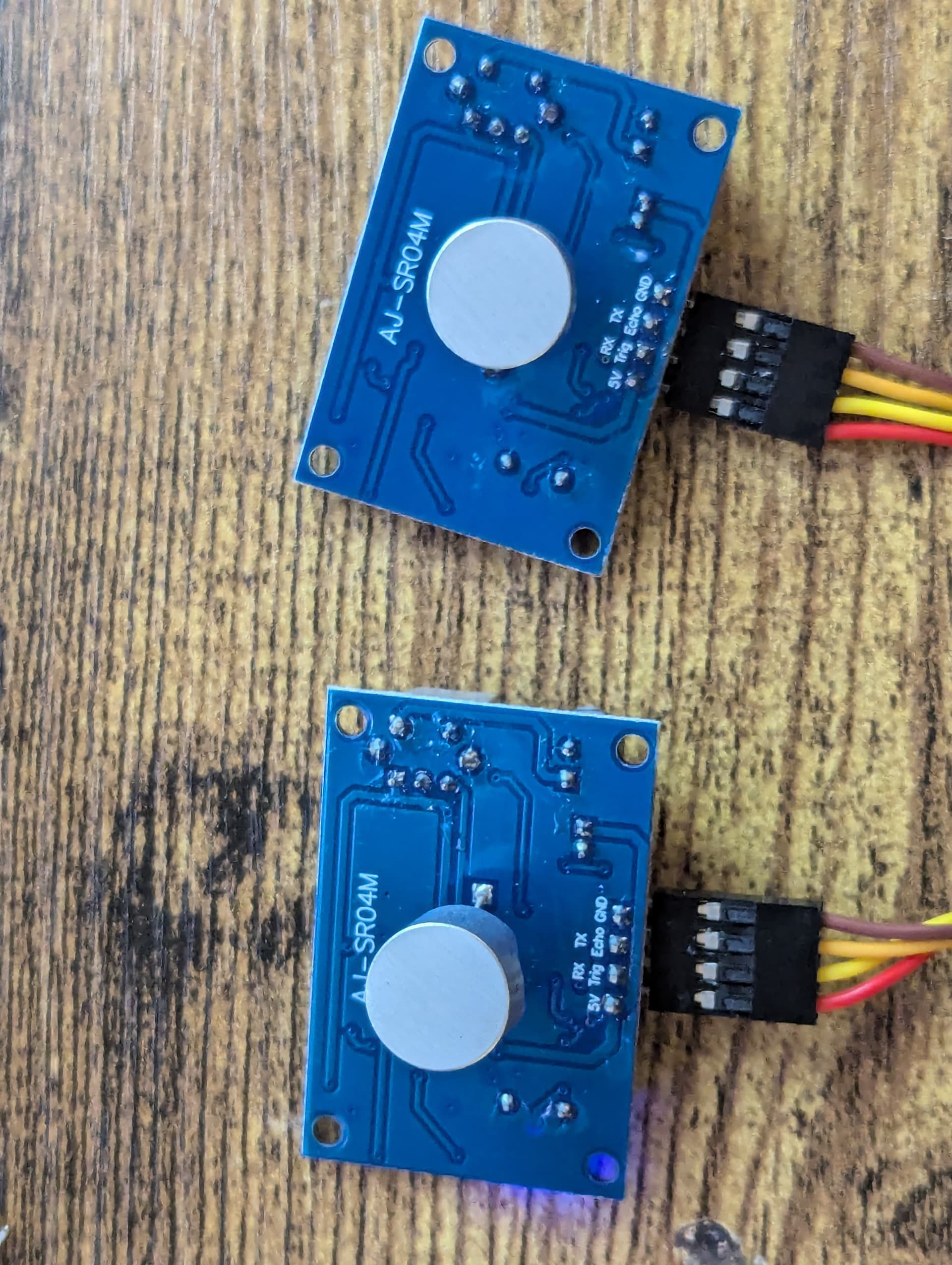
to drive the sonars I have ordered some of these sonar modules that i can use the boards from, as far as i can tell they are clones of the GY-US42 but I havent tested that yet.
https://www.aliexpress.com/item/1005005624952783.html
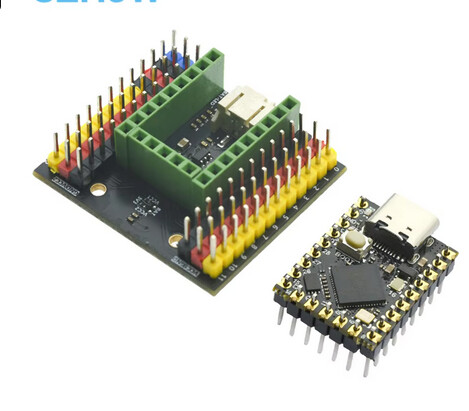
i have bought one of these S3 mini boards for the sub, I was going to use a RP-2040 but the esp32 will make changing settings when It’s closed up much easier using wifi.
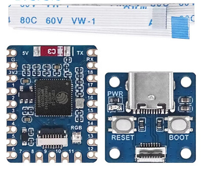
it uses the same pinout as the RP2040-zero so im just using one of the breakout boards for them, the pin numbers are wrong but everything else is fine.
https://www.aliexpress.com/item/1005007385048661.html
I have updated the adapter to use the adafruit MPRLS ported pressure sensor instead of the MS5611 I was going to use.
My new sonar parts have arrived and some initial testing looks interesting, first tests with the RCWL 1005 10mm sonars didnt go well, they really lack any range, and can barely detect a wall 1 meter away, there is very little on the PCB, i don’t see a coil to drive the sonar so I suspect they are running them at only 5v limiting their output power. Testing them with the waterproof sonar transducers wasn’t successful either, I suspect it just didn’t have the power to drive it.
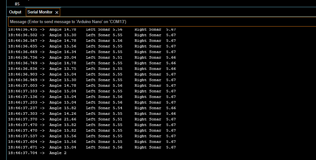
luckily I bought a few AJ-SR04M sonar drivers boards that do work with them and I have a pair of them running using the 2d tracking code.
MSP looks like a dead end. There is just so little documentation on it that I’m ending up trying to reverse engineer it looking at inav source code and getting nowhere.
Next plan is to flash it as ardupilot rover and make all the diving and levelling systems in Arduino. I can get all the sensor information I need like IMU over mavlink and use that to run a pid loop for levelling. Essentially I’m going to copy @U-Boat s setup with ardurover and the separate dive controllers, but because I’m making the controllers in Arduino I can make it a little more integrated using mavlink
For diving I’m going to use the pressure sensor running through a PID loop to control the ballast pump, it can send depth data back using named floats and the mavlink sonar data.
For speed measurements Im still going to use a pitot tube but as far as I know ardurover won’t use that for anything, so an idea was to use a quadrature encoder emulator to generate a quadrature signal that speeds up and slows down based on the water speed so it can use it for Yaxis velocity.
I am going to set up the esp32 as a failsafe device, so it can automatically surface if there is something wrong, so if the battery gets low, if there is no heartbeat from the flight controller, if there is no RC signal it should surface immediately
I had a look at ardusub, but it’s a totally different animal.
1 Like