Hi,
Your new Control Zero Classic flight controller has caught my attention. I saw some information on it in this article below. Has there been a product release date set?
Cheers!
Hi,
Your new Control Zero Classic flight controller has caught my attention. I saw some information on it in this article below. Has there been a product release date set?
Cheers!
Yes, I’m very glad to see that there is a Control Zero solution which has more than 8 PWM outputs, as I need for a VTOL project.  And it is already buyable, isn’t it? But there is only rare information about it, no manual, not even a proper website description, only the shop site (which states it has 14 outputs, but it has only 12?
  ) Also rare activity on their blog lately.
Is anyone using this FC?
I did a pre order.
https://store.mrobotics.io/ProductDetails.asp?ProductCode=M10048D
STM32H743 MCU.
My Freind said the board runs cool that a good thing where i fly for sure.
It’s an H743 with 14 outputs. No IOMCU so all Dshot capable. Like some other H743 boards. Similar stuff in a Pixhawk Case.
Does anyone know which of the PWM outputs share a common timer on this board?
There is a HWdef for it.
Control Zero Classic
Ready to go:
Target
Excellent, thanks!
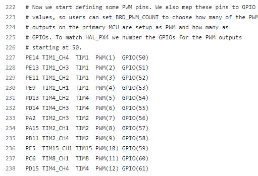
This is the table:
PE14 TIM1_CH4 TIM1 PWM(1) GPIO(50)
PE13 TIM1_CH3 TIM1 PWM(2) GPIO(51)
PE11 TIM1_CH2 TIM1 PWM(3) GPIO(52)
PE9 TIM1_CH1 TIM1 PWM(4) GPIO(53)
PD13 TIM4_CH2 TIM4 PWM(5) GPIO(54)
PD14 TIM4_CH3 TIM4 PWM(6) GPIO(55)
PA2 TIM2_CH3 TIM2 PWM(7) GPIO(56)
PA15 TIM2_CH1 TIM2 PWM(8) GPIO(57)
PB11 TIM2_CH4 TIM2 PWM(9) GPIO(58)
PE5 TIM15_CH1 TIM15 PWM(10) GPIO(59)
PC6 TIM8_CH1 TIM8 PWM(11) GPIO(60)
PD15 TIM4_CH4 TIM4 PWM(12) GPIO(61)
So, to be sure: I can use Dshot for example on PWM7, 8 & 9 and regular PWM on all other outputs, right?
Yea. Nice having a lot of FMU outputs w/o the IOMCU in the way. For some users anyway.
I like the idea of direct replacement of old Pixhawk 1, but for my purposes I’d prefer the newer ‘style’ case (and cables etc.). So, to be sure again, is the Classic - by now - the only Control Zero with more than 8 PWM ouputs or is it somehow possible - official or unofficial - to get out more than 8 PWMs on the other Control Zero variants?
Regarding Cables I setting one up today and they give you all the cables you need. I honestly never had an issue with the old or new conector. So far it been a 30 min setup including setting up Can.
Has anyone flown one of these Classics with anything more than 4 outputs yet?
Having some difficulty with an octo not receiving signals for servos 5-8 (although functional on old mRo Pixhak1).
What is BRD_PWM_COUNT set to?
4, as it was on my traditional PH1 (mRo and Radiolink).
I have a deeper dive into what I’m seeing here, to avoid jacking this thread:
What does the Banner message say in Mission Planner for configured outputs?
Sorry for delayed reply, was away from my units over the weekend and did’t want to feed what I’m seeing before verifying again.
Old Pixhawk 1: BRD_PWM_COUNT = 4 | RCOut: PWM1-12 appears in messages on boot (total outputs 16, total - BRD_PWM_COUNT = 16-4 = 12, expected)
New mRo CZClassic: BRD_PWM_COUNT = 4 | RCOut: PWM1-4 appears in messages on boot (= BRD_PWM_COUNT directly, not expected)
Additionally motor 1 is on the first pin (right-most pin when looking head-on, labeled Aux1), not the 7th pin (labeled Main1)
Try BRD_PWM_COUNT 8. The Pixhawk has an IOMCU so the BRD parameter is setting the Aux outputs for PPM/GPIO. The Control Classic does not have an IOMCU so all outputs look like AUX outputs. At least that’s my guess, I don’t have one of these boards.
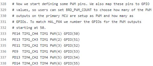
The logic of this from the Hwdef file comments:
Now we start defining some PWM pins. We also map these pins to GPIO
values, so users can set BRD_PWM_COUNT to choose how many of the PWM
outputs on the primary MCU are setup as PWM and how many as
GPIOs. To match HAL_PX4 we number the GPIOs for the PWM outputs
starting at 50.
PE14 TIM1_CH4 TIM1 PWM(1) GPIO(50)
PE13 TIM1_CH3 TIM1 PWM(2) GPIO(51)
PE11 TIM1_CH2 TIM1 PWM(3) GPIO(52)
PE9 TIM1_CH1 TIM1 PWM(4) GPIO(53)
PD13 TIM4_CH2 TIM4 PWM(5) GPIO(54)
PD14 TIM4_CH3 TIM4 PWM(6) GPIO(55)
PA2 TIM2_CH3 TIM2 PWM(7) GPIO(56)
PA15 TIM2_CH1 TIM2 PWM(8) GPIO(57)
PB11 TIM2_CH4 TIM2 PWM(9) GPIO(58)
PE5 TIM15_CH1 TIM15 PWM(10) GPIO(59)
PC6 TIM8_CH1 TIM8 PWM(11) GPIO(60)
PD15 TIM4_CH4 TIM4 PWM(12) GPIO(61)
Yep, have BRD_PWM_COUNT set to 8 and now I can support 8 motors, but the numbering is still wrong relative to the board markings (motors 1-6 on AUX1-6, motors 7-8 on MAIN1-2).
Have not tested yet but I assume that GPIO peripherals (like LIDAR) will start on the remaining pins (in this case MAIN3+). Will report back when I can test.
Where are the other 2 pins in that definition (there are 14 pins present, but only 12 listed in hwdef)? Could I redefine the hwdef to align the outputs back to the board markings?
I think the key phrase in the Hwdef is “to match HAL_PX4 we number the GPIOs for the PWM outputs
starting at 50”
Pixhawk1:
ControlZero Classic:
I don’t know the answer to your other questions. It’s a very different Flight Controller board stuffed into a “Classic” housing.
