How to effectively test a large (25+ kg) Hexa copter before the first flight.
I have been advised to use CompassMot with a current sensor by a LAME.
After reviewing Randy’s video on the subject, removing the 36-inch factory-machined props which have dual-screwed brackets and reversing seems daunting. The input I received was to disable the internal compass, add an external and move as far away from any electrical components as possible that could give off interference.
I have one Here3. Inside the fuselage. GPS 3D lock is solid.
Does doing this negate the need to run CompassMot at all?
If so how would you determine if there is any interference?
To add.
My frame came with 6AWG wiring from the Battery cradle to PDB.
I have a Mauch PL-200 inline voltage sensor with 10 AWG and I have a main line to PDB with 6 AWG. Is it possible to just desolder and cut in the sensor with 6AWG?
Have you flown this copter yet? If so, I would look at the compass performance and decide if you need to use COMPASS_MOT. It’s easy enough to generate the values after a flight using MagFit.
No. This vehicle has never lifted off the ground. In NZ any UAS over 15kg has to be certified airworthy before it can even take off (even if in the middle of nowhere)
Get it to a flyable reasonably tuned state without Compass/Mot and so that you can do some figure 8’s and yaw maneuvers. Then run the resulting log through MavExplorer MagFit utility.
This will give you fine tuned compass and COMPASS_MOT params to adjust.
It’s typical to disable the flight controllers internal compass, assuming the external compass in the GPS unit is a reasonable distance from the power wiring. If they are both close to the wiring, then do as good as you can to start with, then Magfit should sort it out.
I think you could desolder the 10AWG wires off the sensor and solder on the 6AWG - but you will need a serious soldering iron and experienced person that can do it relatively quickly without destroying parts by overheating.
EDIT
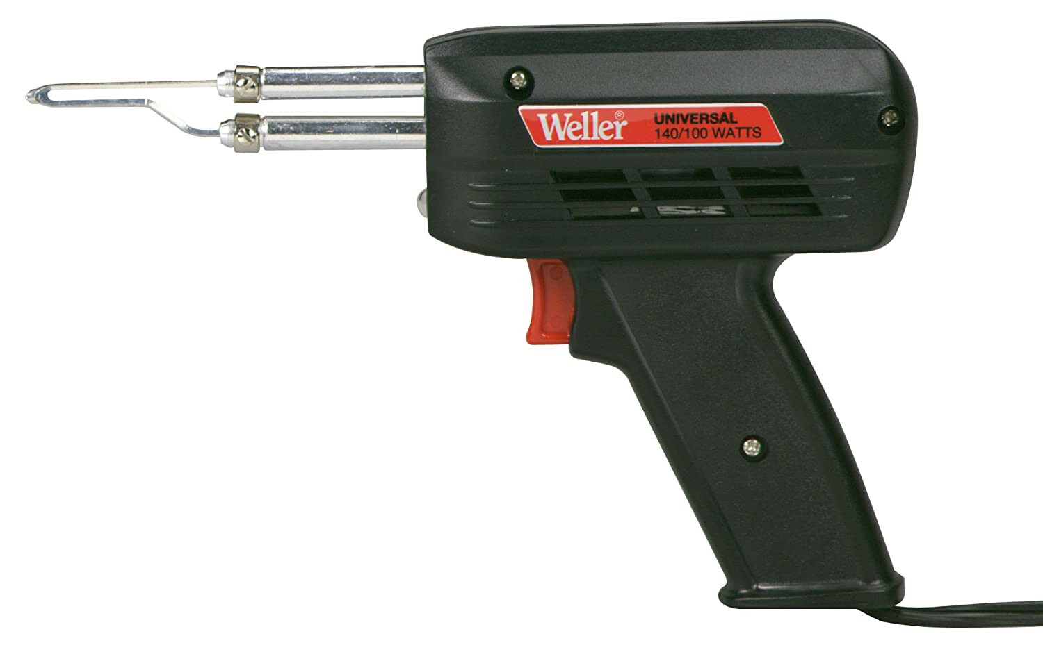
Something like this should do it
Mine is still going strong and has done car battery cables amongst other nasty jobs, it’s only about 30+ years old
Thanks Shawn
Really hard to get to a flyable point without being able to test fly. Go figure NZ is so Chicken & Egg when it comes to testing and airworthiness.
I’m going to try some shielded braiding to see what happens as well. Can’t hurt.
I did get a 120W Pace a while back and it solders beautifully as I needed something for putting XT90s on 12AWG without melting the plastic so I will give it a try. think it was a case of seeing if anyone had success doing this before. I reached out to Mauch a number of times but no reply on that front.
I managed to get the 250A 8AWG version for the Mauch sensor.
I tried to desolder and resolder 6AWG on a previous sensor but it was really just way too heavy grade to be able to fit the wire.
I used everything from point-based terminals to tinning with no luck.
The end result - I used the heaviest grade bullet connectors I could find and soldered an end on to the 6AWG and one to 8AWG and connected that way. I’ve tested up to 95% throttle for 10s at 250A and it hasn’t had any issues as yet and no brownouts. Not ideal in keeping the wiring consistent all the way through but it’s definitely a work around.
Interesting that you mention Pace soldering stations and replacing wires on current sensors here!
I just used my own Pace station to replace the 12AWG with 10AWG wires on a Mauch 100A current sensor. It was no walk in the park, and I should’ve left well enough alone. I did succeed, but it wasn’t a fun job!
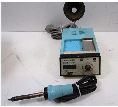
You need one of those good old Dick Smith soldering irons
In actual fact my son sometimes steals mine and takes it (to a place where he’s done work on some very special interesting gear) for those big heavy duty jobs. It gets lots of laughs until they see that it’s done the job.
Nice. That’s old skool! I went for a pretty big chisel to get enough heat without melting the hall sensor.
I would say maybe don’t drink too much caffeine before trying this as it’s super fiddly. I managed to get the 6AWG out fine. and it cleaned up nicely with some solder wick. The hard part is tinning the wire in a suitable way that you can then resolder to the board and subsequently the sensor.
I wasn’t able to use anything smaller than a 5mm chisel to get enough heat to tin and therefore solder 6AWG so I used the tinning pot which had its own complexities. https://paceworldwide.com/1364-chisel-515mm i’ve since decided to also get a digital microscope so I can better see what I’m doing and remove some of the ((((shakes))))