I am working with a drone simulation in Gazebo, where it has a correct orientation (in comparison with other drone models), and now, when I want to use QGroundControl, the orientation of the drone is rotated 90 degrees and it flies sideways. I´ve tried to change it by parameters such as AHRS_ORIENTATION 2, COMPASS_ORIENT 2, COMPASS_AUTO_ROT 0 and I am getting: compasses inconsistent error.
My question is how QGC sets the orientation and how should I manipulate it.
Thank you.
Some of the early models for Gazebo were set up with incorrect orientation and mapping between the ArduPilot NED frame and the Gazebo ENU frame. The relative orientation of objects in the simulation would be ok, but the global orientation would not (for example when comparing to north in a GCS). Things to check:
- ArduPilotPlugin
The frame mapping elements should be:
 <plugin name="ArduPilotPlugin" filename="ArduPilotPlugin">
  ...
  <modelXYZToAirplaneXForwardZDown degrees="true">0 0 0 180 0 0</modelXYZToAirplaneXForwardZDown degrees="true">
  <gazeboXYZToNED>0 0 0 180 0 90</gazeboXYZToNED>
  ...
</plugin>
- World files
Then when including the model in a world file you should rotate by 90 deg if you want the initial model heading to be north:
<include>
  <pose degrees="true">0 0 0 0 0 90</pose>
  <uri>model://iris_with_ardupilot</uri>
</include>
Some of models and world files may still be outdated. If you have examples, please raise an issue or PR.
Edit Tracking fixes here:
Thank you for your response.
The model is of a proprietary drone with its stl file. Other models are oriented correctly, but this one has a wrong orientation of the stl. I wanted to resolve it in the sdf instead of rotating the stl (which causes a bit of weird behavior during flight).
Let me refine description of the problem. I have STL model of a drone. Orientation of the drone during flight in QGroundControl is turned, so it flies sideways. The only way how to fix it is to turn element in SDF, but it changes physical attributes (drone is not symmetrical).
I’ve tried to rotate STL in Blender, but the orientation in QGC and Gazebo stays the same.
Any idea?
@rudolecky the problem is not the orientation of the meshes etc, but most likely the transform between the Gazebo ENU frame and ArduPilot NED frame. Have you tried changing the two elements described above?
If you are able to share the SDF model I would be happy to take a look at it.
@rhys Yes, I´ve checked the orientation for ArduPilotPlugin is set right.
Please see the attached
model.txt (33.9 KB)
sdf file.
Hi @rudolecky,
I’ve taken a look at your model. There are a number of issues that will be causing you problems, not just orientation:
- The element
<gazeboXYZToNED>0 0 0 180 0 90</gazeboXYZToNED>is missing a degrees=“true” so the rotation will be 180 and 90 radians - The IMU sensor is rotated 90 deg about z. It should only be flipped 180 deg about x so z points down. I think your difficulties are arising because you are tryiing to align the physics with the mesh visuals, rather than the other way around. The collisions should all follow x forward, y left, z up in Gazebo (ROS REP 105). Then adjust the visual pose to match the physics. If you try doing the other way about it is easy to lose track of some of the sensors poses.
- The
<script>elements in the visual materials are not valid for Gazebo Garden and Harmonic (I assume you want these versions as we don’t support Gazebo 11 anymore). - The rotor order is not consistent with the frame orientation you have set the IMU to.
- The rotor canting causes issues with yaw authority and does not seem to be consistently applied
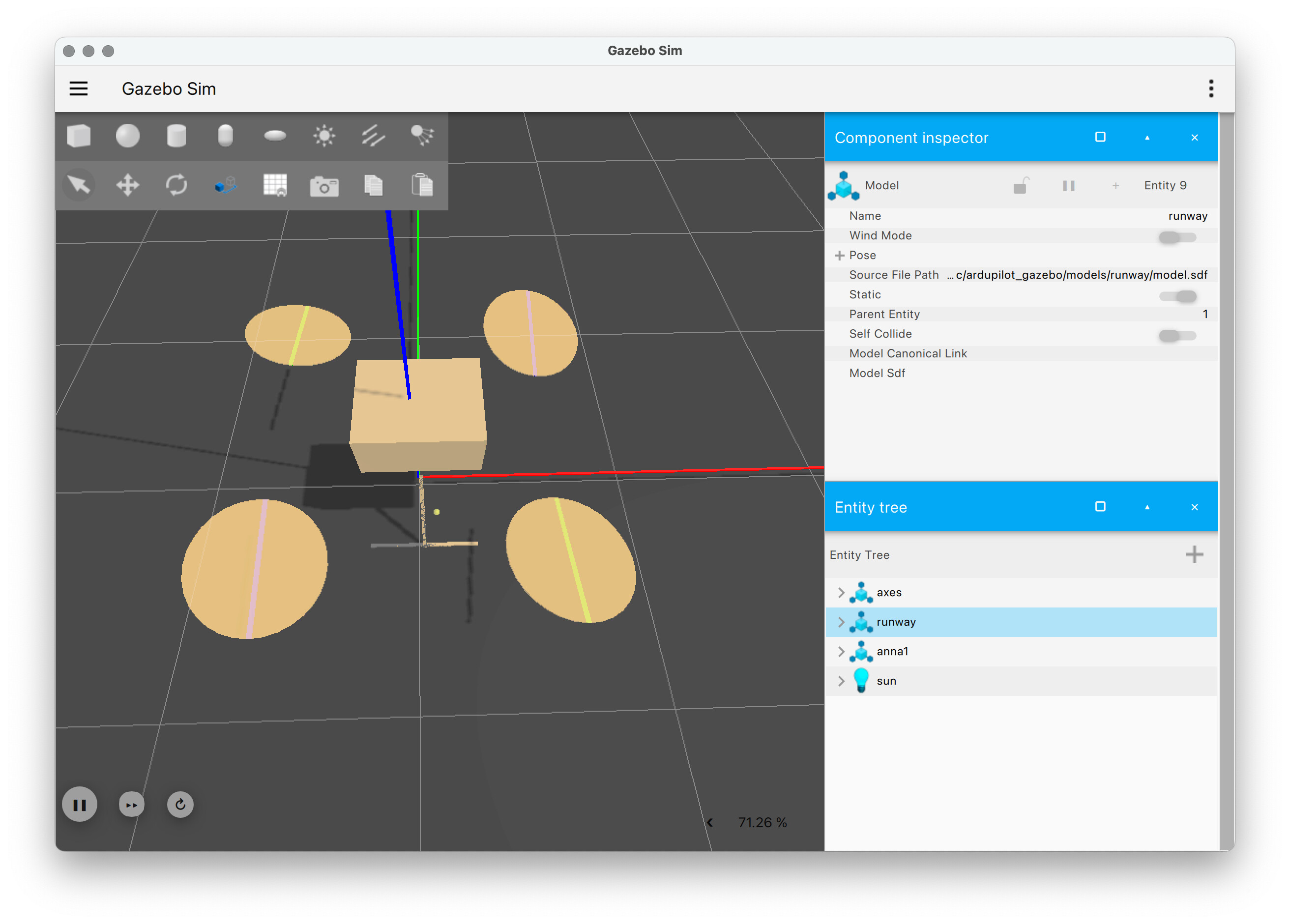
Figure: rotor orientation - exaggerated by increasing angles from 5 deg to 10 deg. The copter is aligned with the ENU world axis - y (green) is North / forward, x (red) is East / right. Rotor order: 1: ccw, top right, 2: ccw, bottom left, 3: cw, top left, 4: cw, bottom right.
I’ve added simple visuals that correspond to the frame collisions and you can see that these are rotated 90 deg. These don’t affect the flight physics. I modified the IMU to align with the rotor order.
If the rotor canting is removed the vehicle flys ok with some PID tuning to account for the larger mass compared to the Iris. With the canting as provided the vehicle will lose yaw authority and not be able to recover. The canting shoulld be symmetric and outward if you want to increase yaw authority for an X - frame.
1 Like