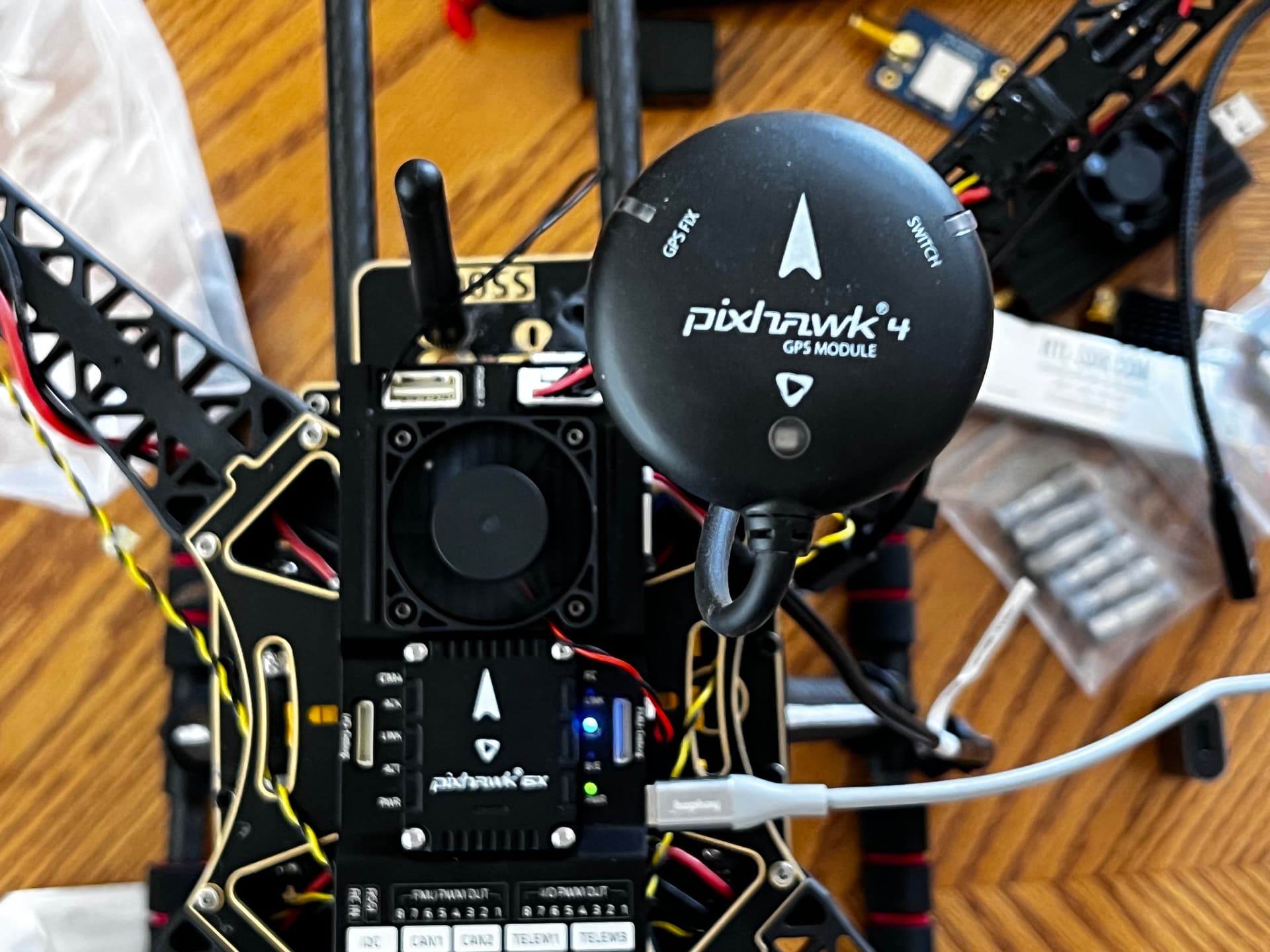
Using a Holybro Pixhawk 6x with RPi CM4 Baseboard. External GPS is from a pixhawk 4 based S500 kit where it had no issues. I did a quick first flight and noticed that the pitch control felt backwards, but all radio settings seem correct. This morning I happened to notice that the orentation on the data screen seemed to indicate it was set up as a + (plus) configuration not X. Only thing I found was that the external compass shows Yaw270 Orentation, but it is not actually set that way. I’m wondering what I should do? Replace the GPS, reorient it to actually be 90º off from forward or a setting on the GPS itself? I tried resetting the compass orentation to “none” but after recalibrating it went back to Yaw270 again.

BTW I have a Here 2 GPS on a hexacopter but it has a different connector and I’d rather not tear it apart.
That’s the correct orientation for that compass/GNSS unit, leave it how the calibration routine set it.
" COMPASS_ORIENT=6 (Yaw270) for proper compass orientation" from the Holybro website
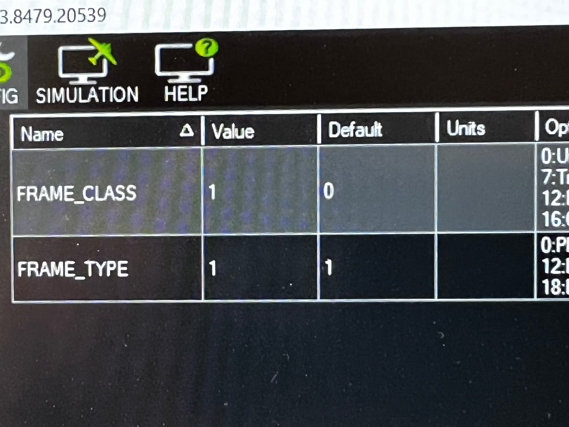
Frame Class and Frame type are 1 and 1 for Quad X.
Is there an actual problem or you were just concerned about that orientation? The Quad X frame symbol on screen might not be completely truthful, but I’ve always seen Quad X symbol for a Quad X.
1 Like
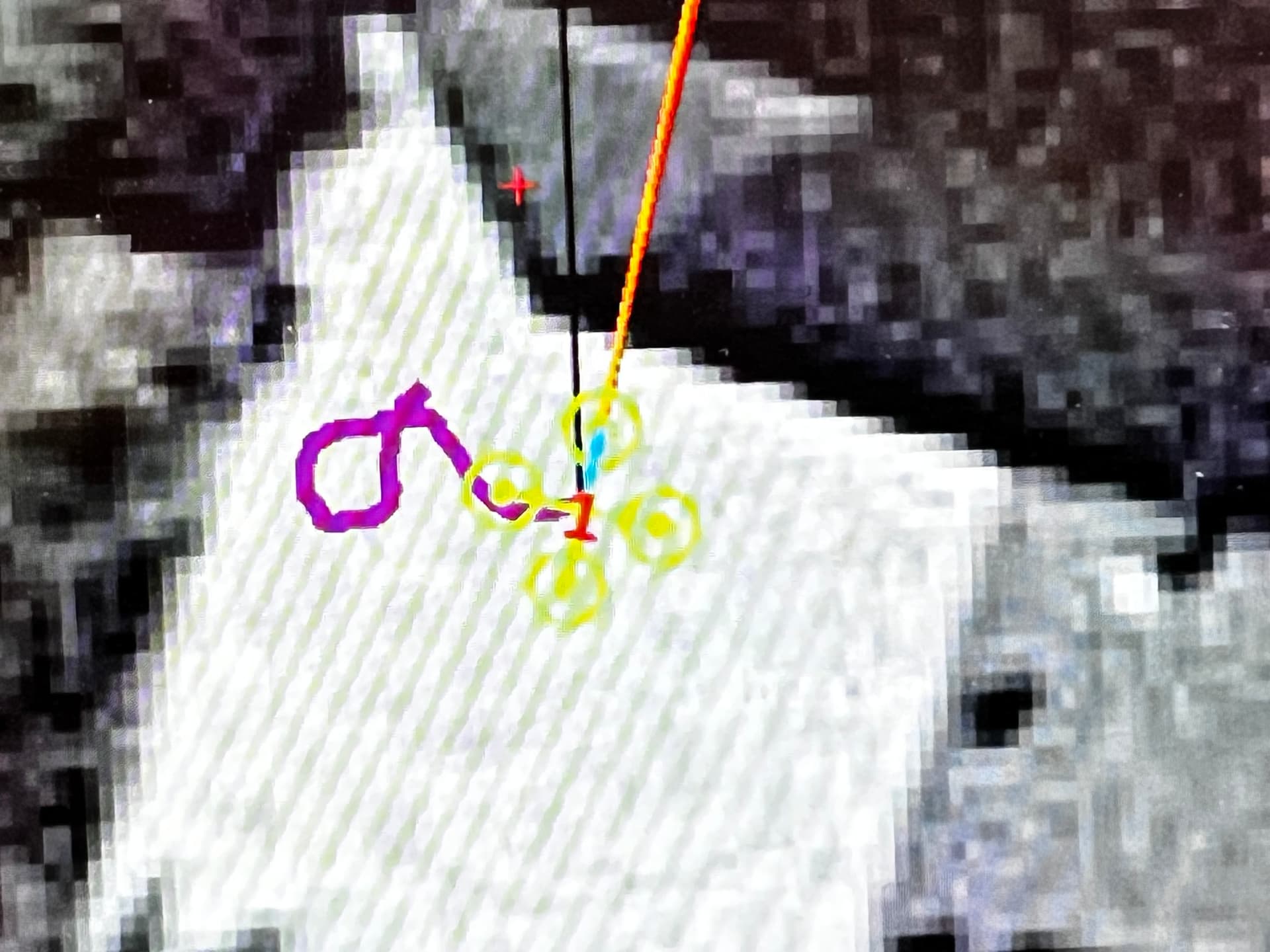
I’m not sure what an incorrect frametype setting would do to actual behavior. Here’s what happend: on the first flight, in loiter mode just to see if it will get off the ground, it felt like the pitch control was backwards (push the right stick forward, aircraft moves backward and vice versa, but I can’t say I was paying close enough attention to it to say for sure it was 100% fore/aft and it was pretty unstable overall for sure needing a good tune, and a little windy too). At first I thought I just had the radio reversed (and that’s still on the table, first time setting up an OpenTX transmitter), but I checked all the places I’d expect to find the radio controls like the calibration page, and they all seem like the correct/normal setting. So while checking everything I could and getting ready for tuning I noticed the alignment on the map looks like it is set up as a + configuration not X, but settings are as shown in the pic.
Mostly trying to filter out the build issues, and make sure they’re not bigger problems. I’ve done builds before (this frame started out as a Pixhawk 4, and I have an orange cube hex and a green cube Solo) but first time with a Tarranis Q7 transmitter (a very big learning experience itself -Herelink is so easy in comparison), mavlink and Raspberry Pi, and now this.
The transmitters pitch channel is backwards compared to what arducopter expects.
Reverse the pitch channel in the transmitter for that “model”.
1 Like
@ReadyKilowatt, may I ask what you are doing with this setup? I am shopping around and I think I am going to get this FC, so I wanted to get your thoughts on it. I want to do some computer vision stuff and I wanted to also add a Google Coral edge TPU, but I cant find too much info on the FC in general. To hook up another microcontroller like the Coral, I am pretty sure I would have to connect it via one of the CM4 Host USB ports and hit that dip switch to EMMC… have you done anything like this?
I’m using it with a software defined radio application of my own design, for mapping small transmitters and RF interference sources. I started out with a Pixhawk 4 that came with the Holybro kit, and CM3 board made by a company called Lime Microsystems, but when I saw the Pixhawk 6x/CM4 carrier from Holybro I thought it would be easier to implement. I now use either a Lime SDR mini or an RTL-SDR board, depending on bandwidth needed.
The docs are fairly Spartan, but basically Telemetry 2 serial connects to the CM4 AMA0 pins. There’s also Ethernet available with an included jumper, although I don’t need that much throughput and use the Pi Ethernet port to connect to the Ethernet bridge on a Herelink 1.1 radio. When I first picked up the board I looked at various micro-sized Ethernet switches but because I didn’t really need the bandwidth I didn’t follow through.
As far as flashing the EMMC, it follows the RPi standard so not a big deal. Just connect your development PC to the CM4 Slave port and it will show up as a flash drive.
The only thing I would complain about is the lack of power options for the CM4. You have to power it over the USB C slave port. Even the power distro board has a USB C adapter. An internal power trace would have made a much cleaner install, although I understand why that might not be desirable too. Maybe a connector/jumper that could be set? Same thing with the peripheral USB C port, it is a normal connector instead of something that has a positive lock tab. To be fair, I haven’t had any issues with the cable coming loose, but it seems like that could happen. Also, if you plan on using the CM4 WiFi radio with an external antenna you’ll need to route the antenna cable out through some other port (I used power 2) because there’s no other way without drilling out the case. As it turned out I wasn’t getting much range out of WiFi (hence the upgrade to Herelink), but I leave it as it is so I can connect on the bench.
I’m probably not taxing the Pixhawk 6x much, but because it was a convenient package it made sense. Very easy to build and tune. Operationally I didn’t notice any difference between it and a Cube after flashing Ardupilot. I’ll probably revisit Ethernet after reading this blog post from earlier this week, especially if I can find a small and cheap Ethernet switch somewhere.
1 Like