ok I made a bit of progress, I used qgc to save a params file from the pixhawk, then edited the file for the few settings that you have in your file.
I guess I could also use qgc to change them in their interface.
ok I made a bit of progress, I used qgc to save a params file from the pixhawk, then edited the file for the few settings that you have in your file.
I guess I could also use qgc to change them in their interface.
I believe QGC and mavproxy use different formats for saving parameter files. There are also tools in mavproxy for comparing parameter files; command is "param diff " and the standalone tool is mavparamdiff.py
thanks I’ll give it a shot
Thank you so much for very helpful instruction! could you tell me how to set the radio transmitter for this? i am using flysky radio transmitter! I am not sure how to set the channel in the radio transmitter for this configuration! Thank you in advance!
@Daro_VAN, I am working on the same basic setup. I have the WLToys V383 like @tridge used for his development. I am using the new Pixhawk 4, and I have had a pretty steep learning curve here. This is actually my first “drone”, it’s even my first R/C aircraft, too - so I’m on a pretty steep ramp right now! I already crashed the thing using the ready-to-fly setup, and had to install new frame tubes - fortunately I didn’t break any of the molded parts that I would have to order from China…
That said, I think I am getting close. I have had the most problems trying to get the motor ESC calibration to work - it was stuck in a thing where it would automatically re-calibrate every time I plugged in the battery. I kept trying things until I finally got it to stop doing that, not really sure how, but it still won’t run properly at all. The ESC Calibration screen in Mission Planner just didn’t seem to work for me. I don’t know if it’s because I have a screwed up setting somewhere, if it’s this motor interlock thing, or what but eventually I set the ESC_CALIBRATION parameter to 0 (which it says you should never do), so it wouldn’t auto-calibrate, and then went through a manual cycle of connecting and disconnecting the battery. That at least stopped the motor from singing it’s tune and failing to do anything, but it still won’t run with any input from anywhere. The only way I can get it to work properly is to plug it straight into the receiver (X8R), then the throttle stick on the TX makes it work just fine - so it doesn’t seem to be the hardware.
After trying everything with out much success, I’m thinking that the motor interlock thing may be part of my screw up here. I set the FrSky Taranis X9D to put the interlock on the radio’s SD switch, and channel 8. I didn’t change the high/low, I just left it at -100 for low (switch up, toward top of TX), and at +100 for high (switch down, toward bottom). Then in my mind down was “interlocked” and up was “non-interlocked”, so I may have this reversed. Still not sure, but it hasn’t made any difference on motor operation.
But at any rate, my intention was to reply to your question about setting up the radio, if you haven’t figured that out yet. It took me several days of studying this to figure out how it all works. The Taranis X9D is so far beyond my capabilities at this point, I was a little overwhelmed by it. I don’t know if this is the radio you have, but I am going to assume that all of the FrSky radios work the same way - but I may be wrong on this, so my apologies if I steer you wrong. Here’s how I did it:
 to realize that because the Taranis is so extensively configurable, all the inputs can be mixed into a channel, and everything can be changed - so you really have to pay attention to what you are selecting.
That should do it, I hope it works for you. At least maybe this will get you introduced to re-configuring the TX.
Good Luck!
@tridge, can you give a brief explanation of what the motor control is supposed to do on this V383 setup? I can’t seem to get anything to work. The only time I can get the motor to budge is when I de-select and then re-select the reverse check box in Mission Planner under Initial Setup, Servo Output for the #8 servo. Upon doing that the motor ramps to full speed, then ramps back to zero - never to work again. Well, at least it runs once, I just can’t figure out why.
I think I understand that the H_RSC_MODE of 2 is a rotor speed set-point mode, and it appears that the H_RSC_SETPOINT value of 800 means 80%, but when is this actually activated? I’ve been through the arming and disarming cycle, and motor interlock enable/disable so many times I am thoroughly confused about it at this point. I thought it may have something to do with the geofence or the fail-safe settings or something, but I have disabled all of that stuff to just try and get the motor to run.
Anything you can do to help will be appreciated.
Brad
Brad,
If you are using the collective pitch quad frame in ArduCopter, then you can get a lot of information about the rotor speed controller from the traditional helicopter wikis.
RSC_MODE 2 is meant to be used for esc’s with a governor. So the value you set in the RSC setpoint depends on your ESC and its governing function. I have only worked with Castle Creation ESC’s and they provide 3 speeds based on the setpoint value.
If you don’t have a governor then you could use mode 3 which is a throttle curve which provides the user the ability to set motor power based on collective pitch input. see the traditional helicopter wiki for more info on a mode 3 setup.
All of the RSC modes use channel 8 on the receiver to enable/disable the motor interlock. So the sequence is have channel 8 low (PWM ~ 1000), arm the aircraft, switch channel 8 high (PWM > 1700 (i’m not sure the exact value you must be greater than)). At that point the rotors should ramp in according to your governor ramp up.
hope this helps.
Bill
@bnsgeyer, thanks for the reply.
I don’t have any information on the ESC, it’s the one that came with this V383, so I don’t know if it has a governor or not. I doubt it, since it’s a pretty cheap one. So I agree with you, maybe that’s a problem. I will try the mode 3 throttle curve as you suggest, and see what I get.
For now, I have been simply using the parameter file that Tridge provided (the same one linked in an earlier post), and as far as I know he was using the hardware that the craft came with. I have the same type of machine he used - on purpose, I didn’t want to start over since this is all new to me.
I would think that the 80% throttle setting in the RSC_SETPOINT would make the motor output go to 1600 since that’s 80% of the 2000 maximum I have set on that servo output, but that’s not happening. So there is something missing in the setup I have.
I also have the channel 8 radio switch set as the motor interlock, but when I do the Switch Low - Arm - Switch High sequence, it doesn’t affect the motor at all. I get no “throttle” response, even though the pitch servos are all working correctly and the throttle control stick collectively increases all the rotor equally. But the motor will not run. I have the #8 servo outputs set at 1000/1500/2000, and the switch changes state in the radio calibration screen, but it seems nothing is being passed to the motor (servo 8 output?) since that never changes.
Thanks again,
Brad
help appreciated.
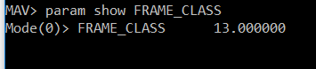
In mavproxy i used the commmand
param set frame_class 13
and then param show as below
but when I test the transmitter to motor relations, and the stability relations, it seems it’s still in standard heli mode. i.e. radio yaw makes servo4 move, and the radio throttle make servo1,2,3 move.
Also when I restart the pixhawk, I notice that it switches back to frame_class 6. So it must never have changed?
Any suggestions?
@brad.wilkinson could you post a param file. I would like to look at your set up. It may help determine what the issue is in arming your motors. Have you looked at the status tab of the flight data page of mission planner. This will tell you what the output to channel 8. it actually has a lot of information on the aircraft and current values for various things. Are your ESC’s even making sounds that indicate that they have been activated. I know my ESC makes an initial tone that tells me it is powered and then another tone that tells me that it is active and ready to start the motor.
Regards,
Bill
@bnsgeyer - Bill, here it is - if this works.
BW_V383_HeliQuad_20180804_0942.param (14.0 KB)
Ok Brad. I have a few things for you
First do you know why your RC1_trim is set at 982. This is your aileron channel or should be and its trim should be the same as the elevator, around 1500.
Next, your RC3_trim is set near 1500 and it should be within 10 pwm of the RC3_min. Also why is the channel reversed? Put this back to 0, indicating it is not reversed. Check the status page and ensure that the rc3 coming in is near 1000 when the throttle is down and near 2000 with the throttle stick high. If this is not the case then change the transmitter to be reversed on channel 3 so the output from the transmitter is correct.
Now onto the servo parameters. change servo8_reversed to 0, this was probably your issue with starting the motors. I assume the escs for all of the motors are y-cables to this channel? I would just set the min and max for servo8 to 1000 and 2000 respectively.
Hopefully that will get you going.
I have looked at the status tab in mission planner, and all of the channels are coming through as expected. The radio throttle input registers properly, and in fact all 4 rotors increase pitch when I move the stick up. The radio calibration page shows everything working correctly, at least according to the mappings I have.
I noticed that the SERVO8_REVERSED is set to 1, so the output is reversed, but that was already defaulted that way in the firmware when I loaded it. I have tried changing that, but it didn’t make any difference for me. I think this is just so that the throttle goes high when the radio switch goes low - and this is basically the “motor interlock” function in a nutshell.
The thing I don’t get is why it won’t go to the 80% throttle setting when I switch the CH8_OPT switch low (to remove the motor interlock). I understand that the throttle stick doesn’t actually control the motor speed, but I still get no motor operation. There was a point in all this when my switching the switch on the radio, or un-checking the reversed box on servo 8 in mission planner would make the motor run up to speed for a second, and then spin down to zero. I could do this repeatedly, so it was getting the message through somehow. But now I get nothing. I have noticed that in this latest setup, the servo 8 output is not changing when I arm and remove the motor interlock, it just stays at 2000 output the entire time. So there is definitely something missing.
The ESC calibration thing simply seems to not be working at all for me. Every time I do the cycle of: power on, wait for flashing lights, press safety switch, listen to musical tone from the ESC - the battery counts - and the long tone, then power down, when I power it back up it goes right back into the same auto-calibration routine and starts the motor music all over again. The ESC_CALIBRATION value stays at 3, it never satisfies itself and resets to 0. I have no idea what I am doing wrong at this point - I have tried this dozens of times. Do you leave the motor interlock CH8 switch high or low during this calibration? Does it matter?
I think next thing I am going to try is setting the ESC_Calibration to zero (normal startup), and change the H_RSC_Mode to 3 as you suggested before to see what I get with those.
Brad,
I know for a fact that the RSC will not work properly if channel 8 is not set to normal. It has to be set up that way.
So the ESC calibration is probably the issue. That does not work for trad heli setups. Please set that to zero and set servo8 to normal and try it
Bill, thanks for your reply.
However, I have a Mode 2 radio, so the settings are correct for that. Throttle is on the left (radio channel 1), aileron (roll) and elevator (pitch) are on channel 2 & 3 on the right stick, rudder is on the left stick with the throttle and is on channel 4. I’m pretty sure that’s why the settings are where they are. These mappings are correct in mission planner, I used the “Calibrate Radio” button to set the values. There, I get the correct roll, pitch, yaw and throttle responses on the bar graphs in the radio calibration screen, and on the vehicle the rotor blades all respond in the appropriate way to stick movements, and to actual vehicle movements.
There is only one motor and one ESC just like a helicopter, this is a single motor collective pitch heli-quad, not a typical quad copter.
@bnsgeyer, OK - I think that did it.
I did the two things you suggested, I set the ESC_CALIBRATION to 0 (normal startup) manually in the parameter list, and I set the SERVO8_REVERSED to 0 (normal).
Also, since I have now eliminated the auto-calibration setting for the ESC, I used the manual calibration method. I connected the ESC straight to the radio receiver, and calibrated with the throttle stick on the transmitter. The ESC and motor work fine that way. This seems to have stopped the endless re-calibration on every power up, and now I can get the motor to run with the channel 8 switch.
When I switch the CH8 switch low the motor is off, and when it is high the motor runs - although it ramps up and down continuously, which I assume is maybe because it’s not connected to the rotors and has no load on it. The servo 8 output is now 1000 at switch low and 1800 at switch high. I would have expected 1600 on the high position with the RSC setpoint at 800 (80% ?), and this switch function seems opposite of what I thought the interlock should do - but whatever works.
It appears to me that in Tridge’s file for this V383 machine the parameter called H_RSC_PWM_REV being set at 1 was to make the motor output low when the switch was high on CH8. The CH8_OPT parameter is set to 32, which is motor interlock, and the notes there say that this is what is performed when the PWM on that channel is above 1800. So it seems that the point of reversing it was to make it work the correct way - where the high state is the interlocked state. But for one thing, this RSC above parameter is non-existent in the mission planner parameters, and like you mentioned maybe the actual RSC module is looking for the CH8_OPT to be low to remove the interlock and allow the motor to run. I had assumed that just reversing the channel 8 servo output would replace the missing H_RSC_PWM_REV setting above, but maybe this was simply the opposite of what I expected.
Anyhow - what a mess to sort through! I’m sure my lack of deep understanding of how the firmware actually operates has something to do with it.
Thanks again for your help.
Brad
@ChrisOlson, I was reading back through the comments here, trying to figure out my problems with ESC calibration and the motor interlock, and I saw what you said here about lack of cyclic leading to lack of auto-rotation capability. So I thought I would re-mention something that the collective pitch heli-quads have instead of cyclic: differential collective. I think you actually mentioned this somewhere earlier, when you were responding to the question about changing rpm of the motor(s), and explaining that it’s not required because differential collective accomplishes the task.
As you are saying, the thing that the cyclic does for auto-rotation is pitch the rotor into a “glide” attitude (for lack of a better description), to keep the incoming airflow in the proper direction through the rotor. Differential collective would do the same thing for a heli-quad - it would establish the pitch of the rotors by pitching the entire airframe, and then overall collective would be used the same as in a traditional helicopter - to flatten the blade pitch or angle of attack and allow for airflow driven auto-rotation.
The CH-47 Chinook has differential collective for pitch, and uses cyclic to roll and yaw. It actually uses “differential cyclic” to yaw, the rotors tilt in opposite directions left and right, and the rotation point can be varied fore and aft, from the front rotor to the rear, by changing the amount of cross-control between roll (cyclic stick) and yaw (rudder pedals). And the Chinook does auto-rotation like any other helicopter - just a good bit heavier!![]() I would think the collective pitch quad would do it the same way.
I would think the collective pitch quad would do it the same way.
So I for one am hopeful that we can get the auto-rotation to work, at least maybe a stabilized descent instead of a tumbling crash. I plan to put the same one-way bearings in the rotors that the electric helicopters use when I build a larger version.
So I’m assuming after you determined the limits of the ESC, you set the servo8 limits to those you found with the direct method and returned your RC transmitter limits back to what they were before this manual calibration method. If you didn’t, then you need to. Otherwise you will affect your collective settings
I’m not sure why it is continuously ramping up and down. So the trick to servo8 output to mimic the RSC Setpoint is to set your Servo8 min and max to 1000 and 2000. Then the RSC setpoint value should be what you set the parameter to plus 1000.
So tridge did this on an older version of software where 1 was normal and i think -1 or 0 was reversed.
Your reading too much into it, the RSC set the servo ranges in previous versions as well as the reverse parameter. This was before we separated the RC inputs from the servo outputs.
When you complete your set up you may want to post your parameter file to help others who are trying to sort through this setup.
Lastly, I would definitely use RSC mode 3, throttle curve. this should help the rotors maintain a constant speed however you must fly it and adjust the curve to get it right. There is no science to it other than listening to the rotor speed as you perform climbs up to max power and partial power descents. @ChrisOlson talks about it in the videos in the tradheli wikis.
Let me know how it goes.
@Kyle Is there a reason you are not using QGC or mission planner? Also please post what your set up is as far as the controller (i.e. Pixhawk, pixracer …) and version of ArduCopter. Also post a param file please.
Thanks,
Bill
Actually, no - the CH-47 does not autorotate like any other helicopter. The rotor inertia is too low. I have three close friends who have flown them (one still is) and any CH-47 pilot will tell you flat out that de-sync means automatic in-air breakup of the helicopter, and both engines out is, quote, “real stable all the way to the crash site”.