I am new to this and just getting started. I’m trying to build a rover for our vegetable farm and I need advice selecting an autopilot. There is lots of advice recommending Pixhawk, and I’m ready to buy one so I can start playing with it. but I’m not sure which version is the best fit for my application.
I plan to use RTK GPS so that the rover can eventually travel down the 66" wide vegetable growing beds without running over any plants. Imagine a table on wheels. Lots of space is need for the plants to pass underneath the table.
It will have independent drive and steering, using three motors. I’d like to use two in-wheel hub motors so that there is lots of space for the plants to go without axles, shafts and gearboxes getting in the way. The front wheels would be free-wheeling and would steer via a servo motor moving an Ackerman steering connection.
I want to avoid skid-steering so there is less of a chance of tearing up turf. Is it possible to program differential into the two drive motors, so that based on the position of the servo steering motor, one tire would run at a few percent more RPMs than the other. The harder the turn, the bigger the difference?
I’m looking for an autopilot that will allow me to do all this and will be easy to use for a beginner. Is there any one version of a Pixhawk that is ideally setup for this rover?
Yes, in my opinion you have come to the right place for your application. One example of ArduPilot using RTK to steer a large machine here. This is my [rover] (https://youtu.be/frFU9pNqIiI) that is closer to your desired design. It has a gas motor but uses two electrically driven wheels. It is a skid steer but the output from ArduPilot can also support steering front wheels as well.
Sounds like an interesting project! The current firmware has no support for the type of setup you are describing. We have a similar geometry on some of our vehicles where we have all four wheels driven independently as well as independent steering motors on the front (6 motors to control in total). This requires that all wheels are coordinated and allows for pivot turning about the centre point between the rear wheels. I have implemented support for this setup in Ardurover and it works well, but our motor controllers have their own velocity/position control loops such that we can rely on a precise, linear response. In order for this setup to work, you need reasonably accurate control of the steering angles and wheel velocities. I would be happy to share/assist if you decide to go with Pixhwak
I see you are using a Pixhawk 4. Of all my choices, should I just go with the 4 as well? Its not clear to me if I should just go with the latest as it is more full featured and more likely to be able to do what I want it to, or would I be paying extra for a lot of features I don’t really need. I need to keep my costs in mind, as this rover will only be super useful to us if we have at least three of them.
The engine turns the blade and a 40 amp alternator I like the pixhawk 4, it’s external breakout and power supply is convenient but the wiring is a bit more complex. After killing two pixhawk cubes, I have added a servo power isolator between the pixhawk and the high power speed controller.
You might be better off with a limited slip differential axle with one drive motor. It depends on how challenging the field surface is.
Thanks so much for being willing to share and assist. I do plan to go with Pixhawk, but I still need to decide which one. It sounds like a really cool setup on your 6 wheeled rover.
The current firmware has no support for the type of setup you are describing
How do I setup a velocity or position control loop?
Does the motor controller need certain capabilities? I’m currently trying to select some motors but have very little understanding of how they interact with the code. Is it such that Ardupilot code tells the Pixhawk what kind of low voltage signals to send to the motor controller, and then the motor controller then translates these into the physical action of the motors for the desired motion? Or does Ardupilot code communicate more directly with the motor controllers.
As for the two drive motors, I’m looking at these
and here’s a link to some controllers for them
What should I be looking for in choosing a controller?
I’m wanting to use two drive motors because an axle and differential will be in the way. This rover will be straddling beds of vegetables. It will be on a fixed width of 66", tire center to tire center, and will need to be close to three feet tall so that it can clear plants between the wheels. Imagine a table on wheels with the plants passing under the table. That also the reason I need RTK accuracy, so that plants don’t get run over.
Yes, that version will most likely work for what you are trying to do. The higher end models have better processors, newer sensors, and more memory but I was unable to measure the difference personally.
Make sure that your drive motors and controllers can go backwards as well as forwards, its a very useful feature.
ArduPilot / Pixhawk outputs PWM signals to communicate steering and speed to the drivetrain. My speed controller mixes those two signals to produce the correct signals for the left and right wheels. On other rovers the steering PWM is sent to a servo motor to turn the steering wheels and the speed PWM is sent to a speed controller to control the drive motor. It skid steer mode, ArduPilot will send separate PWM signals for the left and right drive wheels.
I’m going to order the Pixhawk 2.4.8, and I’ve found some wheel hub 350w brushless DC motors and their controllers that I will try out.
For my steering motor, I’m seeing a lot of steeper motors and their associated driver. These are often advertised as being for CNC routers. Will these do well as a steering motor?
You really want a servo motor of some sort for steering, it will make the setup much easier to accomplish. The type of servo motor will depend on your rover design. This type of gearhead servo is fairly powerful and will work with the autopilot here. Do you have designs or pictures of your rover? Weight is a big factor to consider when designing the drivetrain and steering systems.
Thanks a bunch for the lead on that motor. It was 24v, which matches the drive motors and it had more torque for a similar price as the stepper motors I was looking at, so i went ahead and ordered one.
As for the design, I don’t have drawings, but the design is pretty simple as I’m looking to drive around a tabletop. I’m planning to weld some light tube steel together to make the frame. I’ll weld some forks that will be fixed in the rear to fit the hub motors. The front wheels will be more complicated as they need to turn, but I’m planning to have the servo center mounted to two rods that will connect to and turn a vertical shaft connected to the wheels inside a tube welded to the frame.
The weight of the whole thing is something that will evolve. The rover will be useful to us if it can carry 50lbs, so I’m starting with that weight in mind. Eventually, I’d like to have something that can carry 1000lbs. Also, these rovers will only be useful if we have at least a few of them. So my plan is to engineer by building smaller and cheaper ones, getting the details worked out, testing the limits of those and then scale up the motors, batteries, frame, etc. as we try to get it to carry more weight and/or go for longer. Eventually we should have a small fleet, some of which are more capable than others. We harvest lots of light things, like lettuce, and also heavy things, like potatoes. However, one constraint, even for the smallest rover, is that it needs to be 60" wide. So I plan to build as light of a frame as I can of this size and see what the 350w drive motors and this servo can do.
Hi @Steve1, Sorry for that late reply - I some how missed your question.
With the geometry you propose, the speed of each rear drive wheel will be dependent on the desired steering angle. The angle of each front wheel will only be the same in the straight ahead position. At all other steering angles, the two front wheels will have a different position depending on the center of the turning radius. As you will be actuating the steering with a single motor, you will need to set up your steering linkage such that it achieves the correct Ackerman angle for each wheel. https://en.wikipedia.org/wiki/Ackermann_steering_geometry. Determining the speed for each of the rear wheels will be dependent on knowing the current steering angle. If the response of your steering system is linear with respect to the output command of the actuator controller, then this is pretty straight forward - but likely difficult to achieve. Having direct drive motors with controllers that have their own internal feedback makes things nice and easy because you always know and control exactly where they are and how fast they are going. It is not an absolute necessity though. If the steering response is not linear, then it should still be possible to calibrate the steering output relative to input to enable you to get close enough to the required output speed for each rear wheel. To achieve this will require changes to the Ardurover code. I think that this setup along with the 4 wheel drive option would likely have its uses so I am happy to lend a hand with the code.
Thanks so much,
I am very eager to start looking at code. I have no experience with Ardupilot and writing code for microcontrollers, but I have done some web and database coding and really enjoyed it. I’m hoping the concepts will be similar enough that I can dive right in.
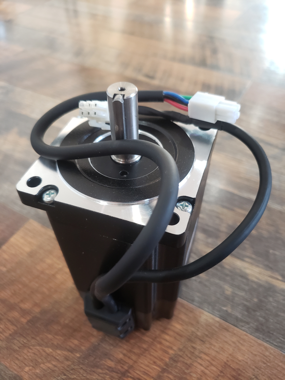
I am still waiting on the hub motors to arrive, but I’ve got a couple of potential steering motors. These have me slightly confused on their rating. I currently have both these:
One is rated at 8.5 Nm and the other at 180kg.cm. When I translate 180kg.cm into Nm, I get 17.65Nm. However the 8.5Nm motor is a much larger and heavier motor. Is there an error in my calculations? I did the conversion online, but I know Newtons are a measure force and kilograms are a measure of mass, so maybe they don’t directly translate.
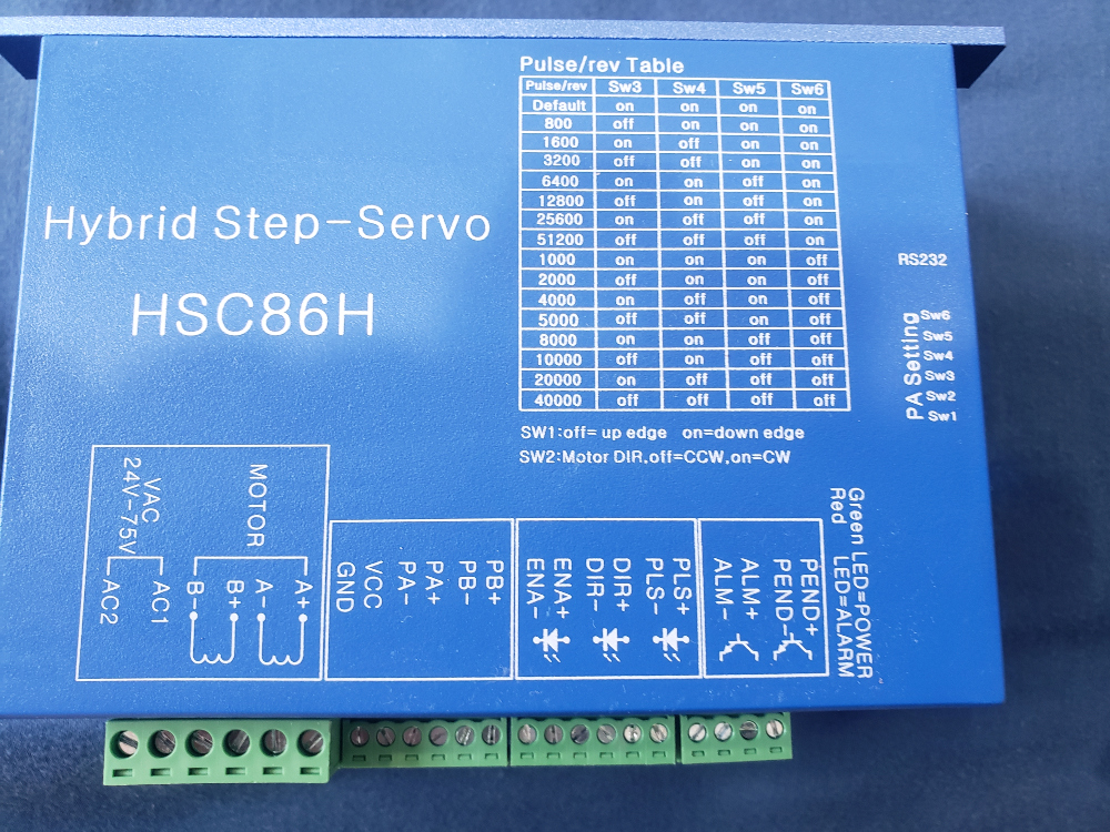
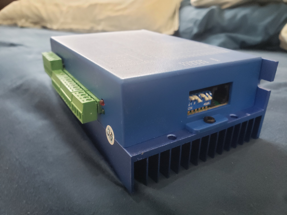
In any case, judging only on size and weight, it appears that the 8.5Nm motor could turn a steering system the size I need for a light machine. I’ve attached a couple photos of this motor and its controller. Does this look like it will work as the steering motor?
I’m also wondering about power distribution boards. Bitdog mentioned a servo power isolator in this thread. Is there something I can buy off the shelf that will allow me to connect the 24v batteries to the two 350w drive motors and the steering motor as well as safely connect to the pixhawk?
Your conversion is correct. The difference between the two motors is the speed at which they will deliver torque. You would reasonably expect size/weight to be related to power output but torque is only one aspect of power, the other being rotational velocity (rpm). It is quite conceivable to have a tiny motor with a very large gear ratio and large torque output. Conversely, you could have a very large motor that spins very fast but with low torque. In either case, you must know both the rotational velocity and torque to assess power output. I think that the higher torque output motor is the correct one for your application. You are not so concerned with rotational speed but you need a decent amount of torque to make sure you can turn as desired in all situations. The 120deg/s rotation speed of this servo should suit you just fine.
Most of the typical Pixhawk power modules should be perfect for what you are doing. These connect to your batteries and to your motors (most commonly using xt60 connectors) and provide the 5v power for your Pixhawk along with current measurement. The Pixhawk need only deal with the signals and not the large currents required by the motors/servos.
What do you recommend for batteries? Since my motors are rated at 24v volts, I am looking for a 24v battery or two 12v batteries wired in series, right? I see options for both Lithium and lead-acid batteries, with the lead acid being a lot cheaper per amp-hour of capacity. Since my frame is large and space wont be a big constraint, is there any reason not to go with a lead-acid deep cycle battery?
As far as connecting the batteries to a power distribution board,how do I calculate the wire size that will connect to the PDB. Since I have two 350w motors- 700w/24v = about 30 amps. This does not include the servo steering motor. How do I calculate the amperage draw for it? Does this mean I will probably be looking at 8 gauge wire for the battery connection?