I have reset my Scale Agusta 109 (800 blades, 10kg, 4-blade main rotor). Now the heli has less weight and less rpm.
This has changed many parameters, including the frequencies of the vibrations.
I use a rotor speed control via the controller.
The speed is therefore fixed and changes only slightly during flight due to torque changes.
The tail rotor is geared 1 to 5.35.
Here I have read through the current tuning wiki pages again and would like to adjust my filters according to these instructions.
Therefore my main question to the forum: May / can I activate and use both filter systems “INS_HNTCH” and “INS_HNTC2” simultaneously?
I ask because I found the following vibration peaks in the FFT display:
17hz = 1020 rpm ==> Main rotor head base frequency.
35hz = 2100 rpm ==> main rotor head 1st upper frequency
40hz = 2400 rpm ==> do not know
52hz = 3120 rpm ==> main rotor head 2nd upper frequency
70hz = 4200 rpm ==> main rotor head 3. u.f.
87hz= 5220 rpm ==> main rotor head 4. u.f.
91hz = 5460 rpm ==> tail rotor base frequency
105hz = 6300 rpm ==> main rotor head 5. u.f.
122hz = 7320 rpm ==> main rotor head 6. u.f.
140hz = 8400 rpm ==> main rotor head 7. u.f
158hz = 9480 rpm ==> main rotor head 8. u.f.
160hz = 9600 rpm ==> do not know
Which filter parameters would you set in this case?
How high would you go supressing vibes?
I link the log file of the corresponding test flight here:
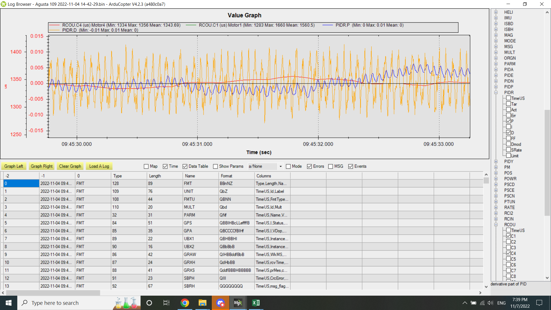
@heri You probably only need to use one of the harmonic notches. The reason being that the higher frequencies are attenuated by the low pass filters for both the gyro and accels which are set at 20 hz. So the frequencies much higher than that are attenuated quite a bit. When I look at your roll axis PID outputs here is what I see
You can see the P and D terms are dominated by the rotor 1st harmonic. If this is a 4 bladed rotor system then you can use the notch filter to suppress the 1st and 4th rotor harmonic. You could include the 2nd harmonic as well to remove the 35 hz peak. Since the tailrotor vibration is so strong (large peak and you can see it in the PID data), you may consider running the second harmonic notch for the 1st harmonic of the tail rotor. I would only set one harmonic for the tailrotor.
I did an autotune for Yaw today with my Agusta. Only the RATE P and RATE D. Not yet ANGL P.
The AT was completed successfully. Unfortunately I could not make a longer test flight because my battery was too empty. But in the short test phase after he AT, I did not like my tail at all. It oscillated slowly back and forth, although there was absolutely no wind (we had a foggy calm autumn day today).
The AT did the following:
ATC_RAT_YAW_D = 0.00515
ATC_RAT_YAW_P = 0.511 and
the ATC_RAT_YAW_I was set to 0.0511.
If you want me to open a new thread for my question to you, please let me know.
Otherwise i would be happy if you could give me some tips about my AT.
@heri I looked at your log and it appears that the new gains were not loaded when you went to test the new settings. I think the P gain that it chose is a little too high. I don’t think it will be unstable but will cause the servo to work too much. So I would say to lower the ATC_RAT_YAW_P to 0.35. Keep your ATC_RAT_YAW_D at the determined value of 0.00515. Although the code sets the ATC_YAW_RAT_I to 0.1 * ATC_YAW_RAT_P, you can keep it at your original value and see if you like that. It looks like it requires some integrator for the hover (meaning that the required hover tail rotor pitch is not at the trim value of the servo). Fly these gains and let me know what you think.
I will have to look at why the code did not set the new gain values during your testing phase of the autotune.
In the wiki for manual tuning it says that you should not set the ATC_RAT_YAW_P value higher than 0.38. Therefore, I had already wondered that the _P value of AutoTuning was determined so high.
I will implement your suggestion and test fly with it and then report to you.
I have changed the parameters as you suggested. At the same time I have prepared everything in the parameters to perform the auto-tuning for ATC_ANG_YAW_P.
With these changes, I made the first flight yesterday, in calm weather. In this flight I first hover a bit back and forth to collect data with your suggested parameter values. Then I switched to the AT for ANG_P tuning. Here is the associated log file for this flight.
The AT for ANG_P for Yaw was successful. The AT changed the following values:
ATC_RAT_YAW_I = 0.025
ATC_RAT_YAW_P = 0.25
ATC_ANG_YAW_P = 10 !!!
The ANG_P value has been set very high. Is this still normal? And also the RAT_P and the RAT_I value has been changed by this autotuning, although I tuned ANG_P. This confuses me.
After this AT flight, I did another flight afterwards. Here I flew a little back and forth in different modes. Nothing spectacular.
You can find the log file here:
Overall, the behavior of the tail has improved. However, I am not completely satisfied. When observing the tail during this flight, I still noticed a slight overshoot when I either changed the torque (by ascending or descending the heli) or when stopping a deliberate rotation of the tail.
What can I do to improve this?
I think that I should increase the RAT_D value?
What is your opinion?
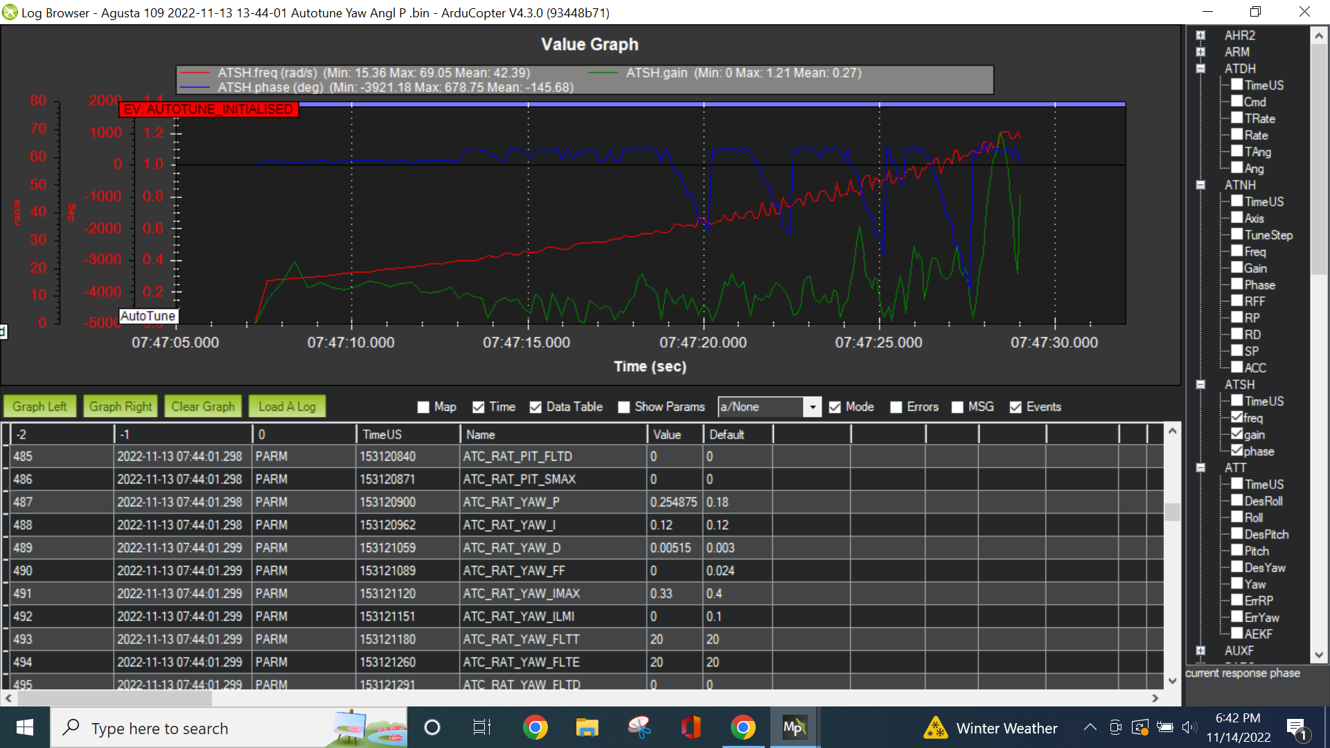
@heri the autotune did not change the ATC_RAT_YAW_P. It did change ATC_RAT_YAW_I because it adjusts the I gain based on Rate P gain. The YAW_P gain was changed before the flight. The picture below shows the parameters that are written to the log at arming.
So maybe you accidentally changed it to this value?
As for the ATC_ANG_YAW_P, the autotune didn’t find the max response gain correctly and thus it didn’t tune the angle P gain correctly. After looking at your angle P tuning log again, There is something that is not right. The response gain is very low and it seems to lag the input quite a bit.
I looked back at the yaw tuning of rate p and rate d. It showed that the rate P gain of 0.5 only produced a response 30% of the request and this required 60% of the servo output. Is this a standard kit helicopter? From this data, it appears that the mechanical gain is too low or the tail rotor speed is too low.
Here is the parameter file which I had prepared for the auto-tuning of ANGL_P and saved on my computer like this (I always save the actual state before I do test flights).
Here you can see that I set ATC_RAT_YAW_I = 0.12 and ATC_RAT_YAW_P = 0.35. Just as you suggested to me.
It would also be strange if I manually entered a curious value of 0.254875. Don’t you think so?
I can only assure you that I do not want to send you on a wrong track here!
It is strange.
What I already noticed with all autotuning flights: After the autotuning flights (even before disconnecting the battery), I connected the FC to my computer via a USB cable and I read parameters from the FC into the MP. When I did this, the MP displayed a parameter list where the test values I had flown always appeared twice. There were always two lines with the same value displayed. But only with the values flown by the autotuning. I thought nothing of it so far.
I always did this on our flying field, immediately after the test flight.
At home I connected the FC again to my computer to download the log file and to save the parameter file. At that moment the effect was over. Everything was as usual.
Regarding your question about the mechanics in the Agusta 109.
No, this is not a standard mechanics. As so often, no standard mechanics of a 3D mechanics fit into the fuselage. The mechanics is “custom made”. The tail rotor speed lis at 5350 rpm. The blades are 125 mm long. That should actually be enough. However, the Agusta 109 has a very large tail fin. This of course obstructs the rotor jet. Maybe the servo travel on the tail rotor blade adjustment mechanism is not large enough. I will check this again.
Is the flown ANGL_P value therefore useless? It is very high with a value of 10? Should I set it back to 4.5?
@bnsgeyer
Bill,
I have another thought going through my head right now:
In your previous post you note that my basic setting of the angle of my tail rotor blades is probably not correct. For this reason I would need some ATC_RAT_YAW_I .
You recommended that I set the I value to the default 0.12.
Just before the helicopter takes off, I always notice that the tail rotor thrust pushes the nose of the helicopter to the left. With a left-turning main rotor, this would mean that the angle of the tail rotor blades in the basic position is too high.
Can I find out from a value/parameter in the log file, if the basic setting of the tail rotor blades is wrong? And if so, can I find out from these values in which direction I have to change the basic setting?
Since you are following the design of the full scale aircraft, I would suspect the tail rotor is on the left side of the tail fin. If you are confident that the size and speed of the tail rotor is comparable to that of a similar size RC heli then I wouldn’t think that is the issue. Check to ensure that you are getting the same amount of blade pitch change as you would with an RC heli.
It may not be representative once you improve the control sensitivity. So yes, set it back to 4.5
No. This has nothing to do with the I gain. You have a mechanical setup or tail rotor thrust problem. It can’t be fixed in the software.
@bnsgeyer
Thanks for all the effort you put in for me.
I understand that I have a mechanical problem with the basic tail rotor pitch setting. I can’t solve that with software settings. I am aware of that.
So my question was aimed at finding out from the log files how big the error is and in which direction I have to adjust the mechanics to fix the error.
At least you can see from the log files that there is a mechanical problem. If you could not have recognized this, then you could not have pointed out this problem to me.
So please my question again: From which log file parameter/value did you recognize that I have a mechanical problem with the tail rotor angle setting?
I would like to increase my knowledge so that I can recognize such an error myself in the future.
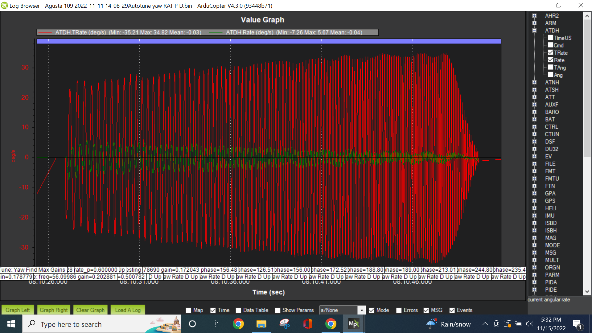
Look at the plot above. I plotted actual rate and target rate from the autotune frequency sweep. You can see that that actual rate is way below the target rate.
In the plot above you can see that even with the last dwell where the P gain was around 0.55, the Rout which is the CMD signal here was around 0.4. Again the actual rate is 9 deg/s and the requested rate is 30 deg/s which is only a third of the requested rate. With that much P gain, the actual rate should match the requested rate. or at least be close (90%).
I can now also see that the required RATE cannot be achieved by the mechanical system, although the software does everything to achieve this RATE.
Your conclusion is therefore that the mechanical system is not capable. I now also understand this.
What is not clear to me yet, how you recognize on the basis of the I-value that my servo center is not correct. I believe you that this is so! But how do you recognize that?
Either way, I checked the tail rotor mechanics and servo travels yesterday.
I found that I have too much angle on the tail rotor blades in the servo center. I have corrected this.
In addition, I have increased the adjustment range on the tail rotor again a little. I am now at the mechanical limits of the tail rotor adjustment.
I will reset the ATC_ANG_YAW_P to 4.5. I will leave the rest and make a normal flight with it today.
Just to see if these above corrections help.
I will post this log file here then.
I also ordered some longer tail rotor blades. These are now no longer sysmetric but semi-symmetric. These blades have more power in the counter-torque direction at a comparable angle compared to the sysmetric blades.
Semi-symmetric blades are popular for scale helicopters.
For any control using a PID controller, the purpose of the I term is to take out bias over the long term. For the case of the yaw axis. the rate controller PID is used to control yaw rate. However the P and D terms may not make the response exactly match the requested rate in a steady state condition. So the I term is used to do exactly that. It nulls the error over the long term (steady state). When I viewed your log, if I see the yaw control output (Yout) is not zero then I know that the tail rotor blade angle at trim was not set up for the value required for hover.
Maybe I didn’t explain myself well here. you need to increase the full travel of the tail rotor blade pitch by 5 times what it is now. So if the current travel is +/- 10 deg for servo min to servo max then it needs to be +/- 50 deg. Or at least double it. Hopefully that makes sense.
thank you very much for your detailed explanations.
If I understand you correctly, you are of the opinion that my servo is not able to make the angle change (RATE) fast enough during the AT. Do I understand this correctly?
I actually have a very fast Futaba servo, which was specifically designed as a tail servo by Futaba. And the linkage mount is all the way on the outside of the servo arm. Actually the servo should be able to change angle very quickly. The only drawback is that the tail gear is not controlled with a carbon rod, but with a steel wire in a plastic tube. In scale helis this often cannot be solved in any other way.
However, since I trust your expertise. I took another close look at everything. I noticed that when setting the servo travels for the first time, the hover pitch is no longer at the center of the servo. The servo is very much off center when the tail is at hover pitch. This results in one adjustment side being very under-proportional and the other adjustment side being very over-proportional. This could be the problem. Sometimes you are just blind.
I have now rebuilt and changed this. I will do a test flight with it and upload the log file here.
ok, so it is about the maximum angle adjustment of the tail rotor blades after all? Of course these are related to the maximum angular adjustment of the servo travel.
The servo travel was already set to maximum so far. However, the servo center of the servo was severely misaligned to one side off center. Therefore it came to very disproportionate deflections to the right and left side. This led to the fact that the tail blades could be adjusted a lot in the counter-torque range and very little in the co-torque range. In addition, the angle when hovering was much too high (As already reported).
With a 3d helicopter, this would have been noticed immediately. In the scale range, one flies just with small deflections on the tail. The Agusta 109 was built a few years ago and previously flown with a standard tail gyro. That actually went quite well.
The FCs are much more sensitive to mechanical errors.
I have now adjusted the servo center back to the middle, so that the deflections are the same in both directions.
When I have made all the other corrections, I will take pictures of the situation and upload them here.
After that I’ll make a test flight and upload the log file of it. In the moment, the weather is against me.