Building a quad frame on the basis of topology optimization

image

BUILDING AN OPTIMIZED QUAD FRAME

In some way this blog is inspired on the very excellent job that did rob215x Robert Giordano in his post building a better quad frame and how to build the lightest ardupilot microquadcopter by Hugues. I must say that I won’t be able to make such nice video intros, but I will try to do my best with FEM and Engineering design.

What is the aim of the Project?

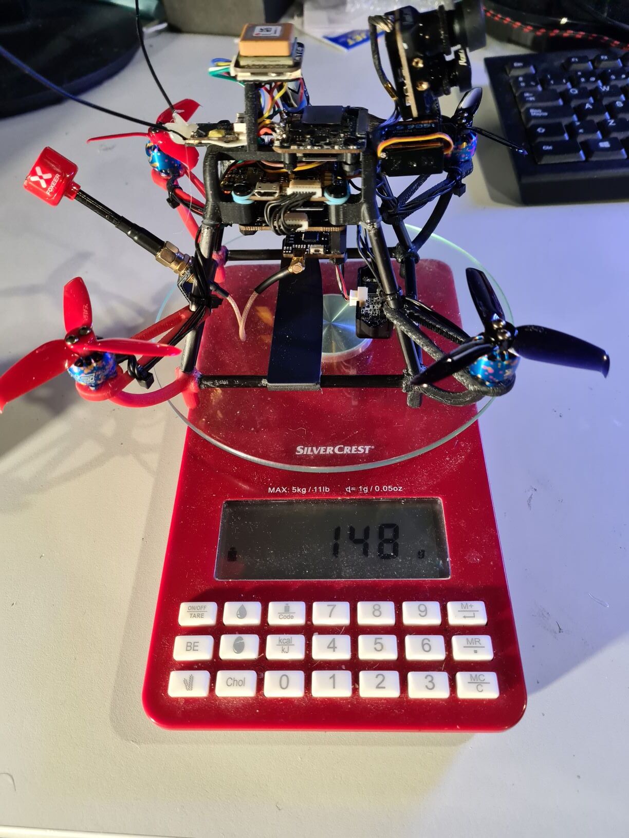
  • The goal is to build a drone under 250 g. from scratch
  • To make the design as light as possible, the frame will be designed under the basis of topology optimization
  • The frame must be as light as possible while keeping enough strength and rigidity.
  • The frame should support at least bad landings
  • CAD, FEM and topology software should be open software
  • Learning about material resistance
  • Learning about anything related with drones

Project background

With topology optimization we should be able to answer these questions:
Why are most of the frames have a flat cross to support the motors?
Is the X frame the best design or would be better a carbon fibre shell?
What is Topology optimization?
Will the drone be able to fly?

Topology optimization

Topology optimization is a numerical method that optimizes material layout within a given space and within given loads and constrains to maximize the performance of the system (usually, the best relation between stiffness and weight). Let’s see an example.
image

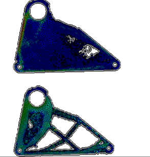
This kind of magic is nice but it is not so easy. First, the result could be difficult or much more expensive to manufacture. Second, this method is hard for computers. A small part takes hours to get a result on an average computer. The result is mesh dependent, and also variations on loads or constrains could show different or inaccurate results.

It would be great to bring this technology to the frame design, wouldn’t it?

Let’s Begin

The first step is to design the maximum available space, so the computer has the possibility to use material anywhere. The blades produce a design constraint. To minimize the constraint a four blade propeller should be better, but efficiency should be worse, so I think I will use three blade propellers. Distance between opposite motors: 150 mm. (But should be scalable as smaller is lighter).
image
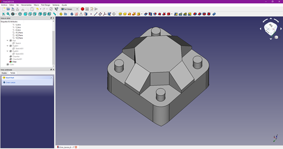
This block is conservative, as I can be sure that no material outside this container would help to increase rigidity while lowering weight.

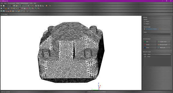
Second step: Generating the mesh.

Topology optimization is very dependent on mesh quality and element size. Due to hardware limitations, I can only choose maximum element size of 4 mm. for a tetgen mesh. 2 mm. could give more detailed results, but my computer can’t stand it.
image

Forces estimation

  • Up: Each motor 1,50 N.
  • Down: In a case of a free fall from one meter, the motors could generate a force down about 15 N. (Maybe too conservative).
  • Lateral forces: Changes in yaw generate forces on the motors. These forces are lower than 1 N.
  • Moments: The changes in the motor speed generate a moment in the z axis equals to 0.011 Nm

Solver

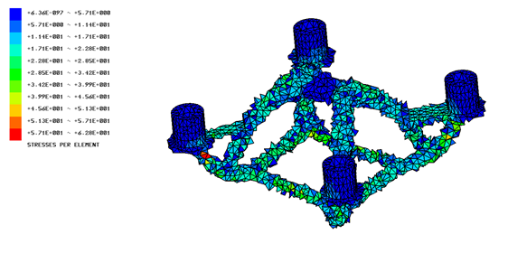
With these data, the computer can make its calculation. For this model took about 17 hours, and we got…

Conclusions

  • This is what computer says, and of course, it can be wrong.
  • If we assume that it is not completely wrong we can say:
  • The best frame is a hybrid X.
  • The arms that support the motors should not be flat. Instead, they should go up to the top of the frame.
  • The design can be made with a 3D printer or with carbon fibre tubes.
  • We could mount easily the FC, ESC, in the centre, under the top and therefore, the electronics will remain protected.
  • It will be easy to hang the battery from the lower square. This square can also be used as a landing gear.

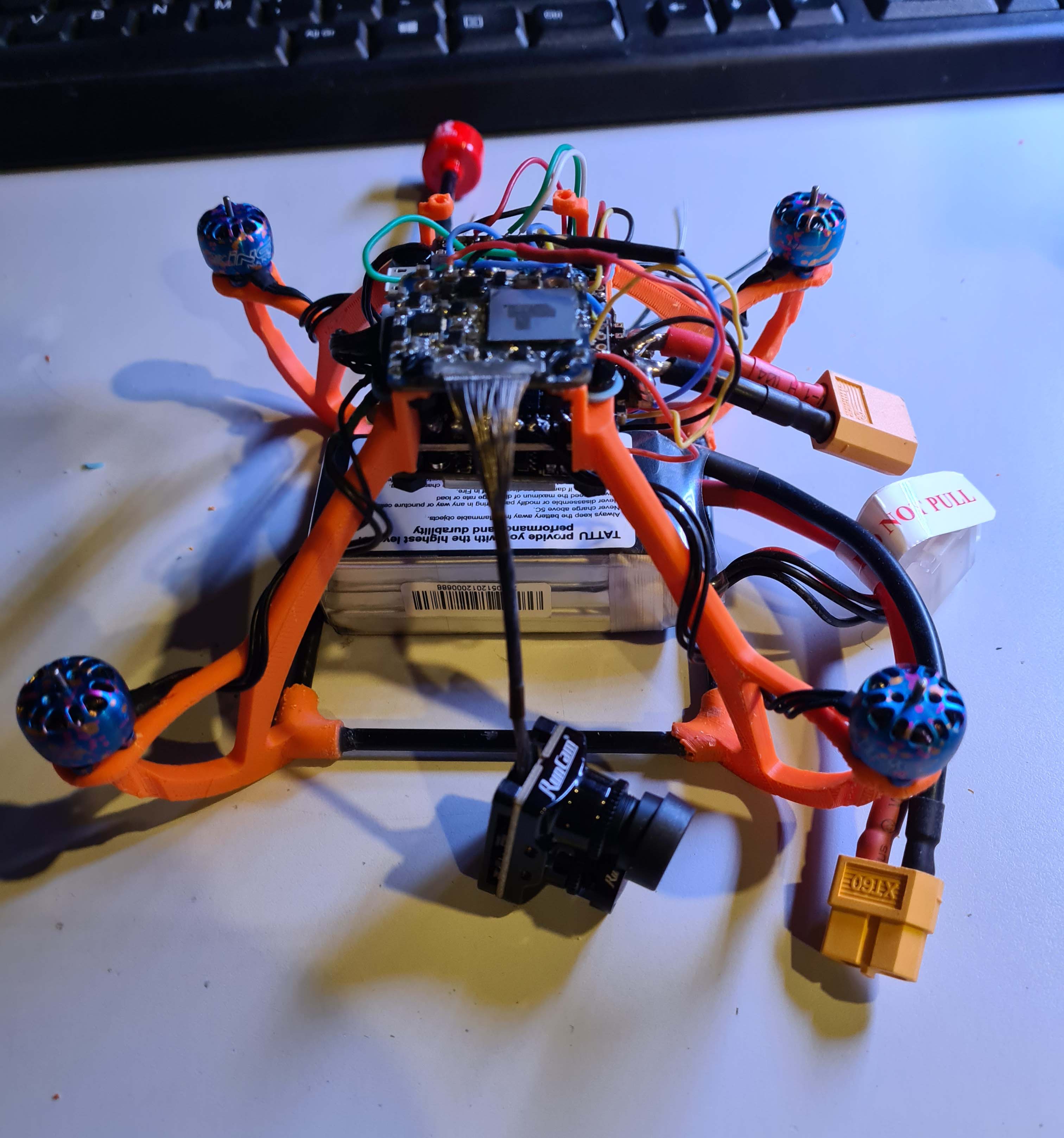
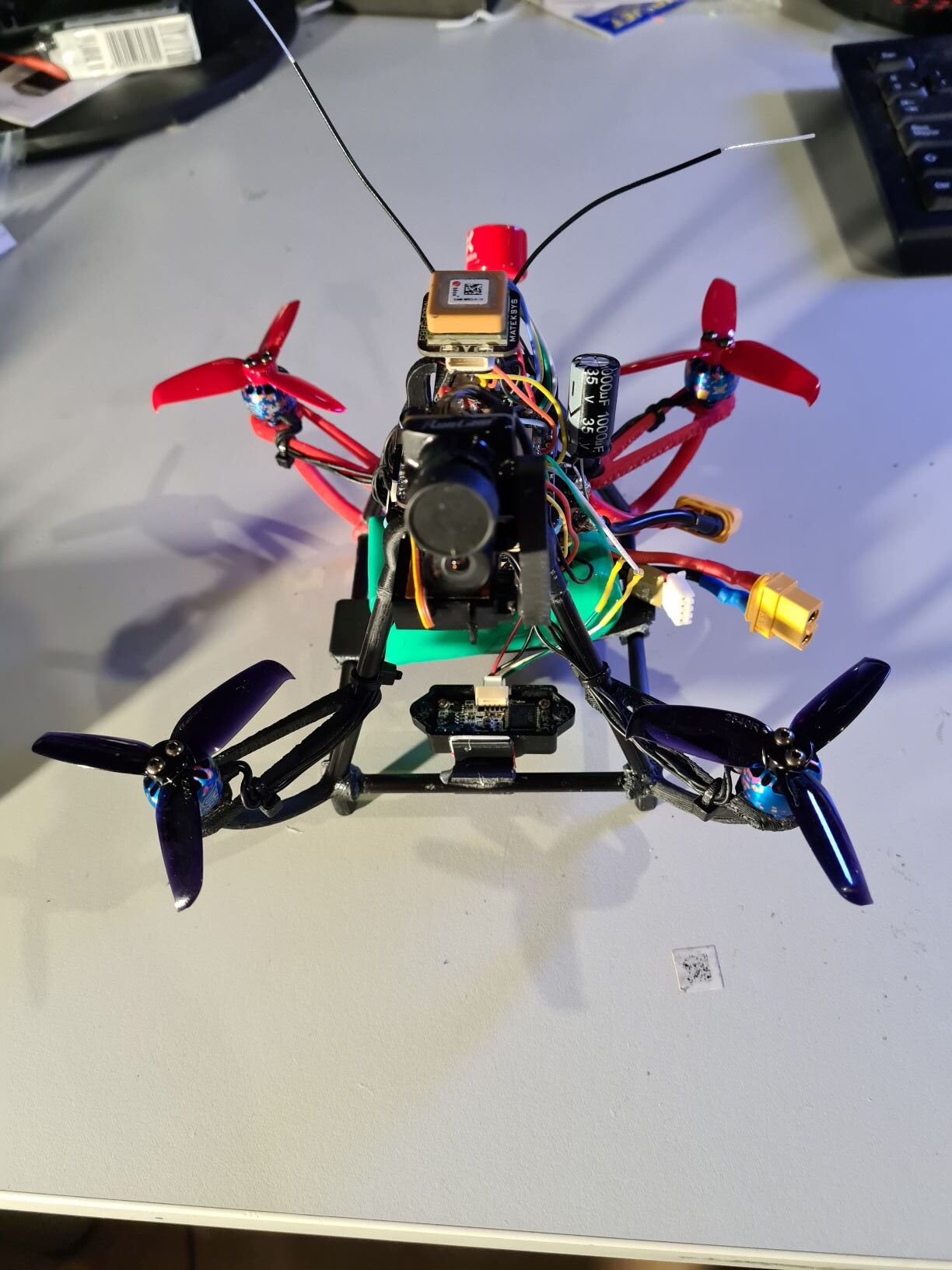
Next level: From design to reality

To be continued.

8 Likes

Interesting approach. I wonder what the results would be if you started with a different shaped block of material. Would be inetresting to see what the results would be with a thinner block and a thicker block?

I like this kind of approaches. When I watch your video, when you rotate the model, I am seeing resemblance with a medieval 4 candle holder, swinging on a chain in a medieval castle, while the knights are having their dinner at the round table underneath. Just kidding, but I also like how your model has interconnections between the arms at the end, and the support structure under the motors. My intuitive mechanic insights tell me this could be worthwhile following up on.
grtz
John

For topology optimization you should go with the maximum size available so the material follow where the forces are transmitted. I have been conservative in this way, (if you watch the first steps of the optimization, the outer part of the block is removed) so a thicker block would give the same result.

A thinner block probably would lead to a more triangulated truss design.

I was a bit surprised because the result was quite simple and quite easy to manufacture. One of the problems of topology optimization in engineering is that the results are optimized for the material but more expensive to manufacture.

Thank you for your interest.

Andres, whats your guess on resonance and vibration on this outcome. If I understand the process correctly, it uses force / strength optimization with minimum material. Which I would guess gives the optimum stiffness with minimum material. Seen the outcome, I think the frame resonance and vibration which is hindering most of us could be of a another universe with such frame.
Just some reflections, grtz
John

ps: I would be curious what a hex would look like, but I assume similar candle shape, wondering how the arms would be connected on the bottom part.

Yes, this is exactly the aim of topology optimization. As this frame is feasible, I will go on with the project. My next step is buying the components. Probably:

Kakute K7
ESC 4 in One
Xing Nano 1105 or Brotherhobby 1106
3 blade 2540 propellers
3S 1300 mAh Battery
Hybrid 4K Camera

Then with the exact components I will make two frames. One 3D printed with ABS and the other one with small carbon fibre tubes for minimum weight.

As you have asked, once its done, I can try to figure out the natural frequencies of the system.

As far as I know, frequencies arround 8 Hz are bad, because the foam of the FC can’t absorb them.In a quad, there are also vibrations with a frequency of 3x the motor speed. (three blades). So, I am pretty sure (although I have not calculated yet) that both numbers would be far enough from the natural frequencies of the system, so I don’t expect any issue with vibrations.

1 Like

Part II: From design to reality

Too much time later I had some time to work again on my project.

I 3D printed the arms with ABS and glued the low square with carbon fiber tubes.

I was not completely satisfied with the printed part details, specially around the holes, but it was good enough to keep the dimensions and build the components.

The goal was a chasis with a maximum weight of 15 grams and the result…

Each of these plastic arms weights around 3 grams which is a great result. Ihave some spare parts to check the mechanical resistance, but I guess it is high.

Part III: Almost assembled

I will try to keep the cables tidy, but all my drones look like flying wires.

Some more pictures when finished…

Part IV: Improving the results

This copter could fly well, but I think it could be improved, so I changed the main diagonal arms with a carbon fibre arm. The main frame was 14 g. but the new one is 10 g. It is only 4 g. but it is a weight reduction of 30 which is a lot. Also the stiffness and strength have been increased.

Finally the weight has been optimized. Even if the main goal was a copter below 250 g. I also wanted some nice staff such an Hybrid Run cam mounted on a servo to change the view angle, and a TF Mini, and finally…

This copter will made its maiden flight the first of january.
Let’s check vibrations and handling…