For a puller setup, the propeller in the front of the plane will affect any airspeed sensors behind. I am considering two ways to set up airspeed sensors.
1: put the airspeed sensor on one side of the wing
The problem is that if you turn left and the sensor is on the left side you will read a lower value and vice versa, which can be significant on gliders. Putting the sensor closer to the fuselage can decrease such “turning error”, but this also brings the sensor closer to the airflow of the propeller.
The question is: Is this “turning error” comparable to other types of errors like temperature-caused value drift? Is it acceptable? How to get the balance between putting the sensor close to the fuselage and close to the wing tip?
2: Set up two sensors on both sides of the wing
The problem is that ardupilot seems to only be able to use one sensor as the primary one and the other one for redundancy, but the reason to use two sensors is that I want a speed value of the blending of the two.
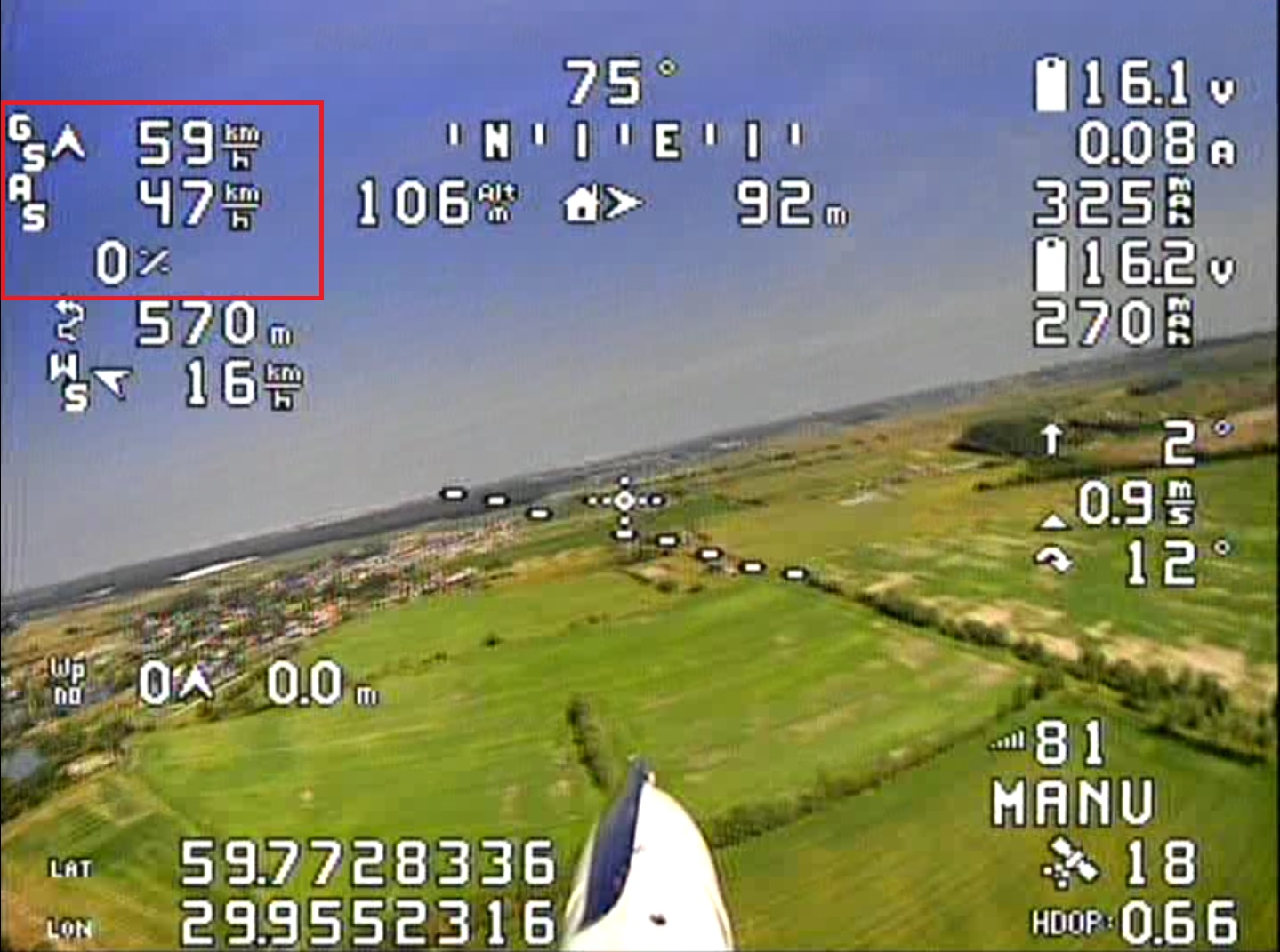
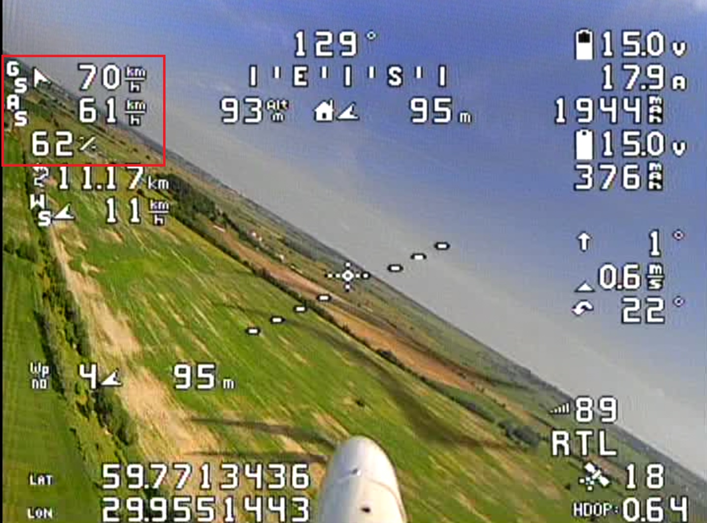
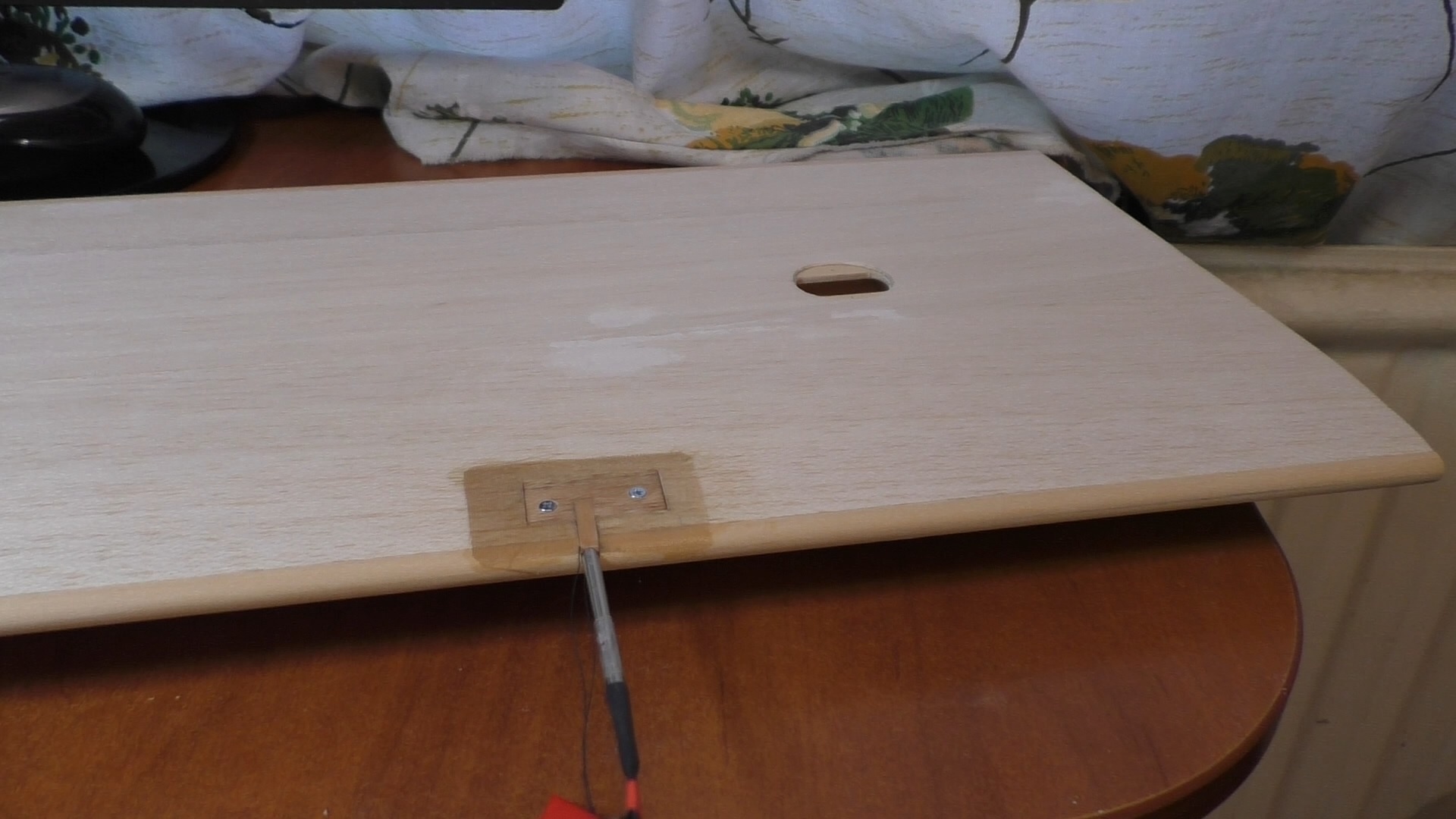
This is my way of installing the speed sensor. The glider flies in auto mode this is an effective method of checking the correct installation of the speed sensor.
In a coordinated turn, there should be minimal difference in measured airspeed at each wingtip. It is common practice to use wingtip pitot tubes in manned aviation (even in some extremely high aspect ratio wings).
Is it just me, or is the artificial horizon in the OSD angled the opposite way from what it should be in those images? On mine the dashed lines are fairly well aligned with the actual horizon.
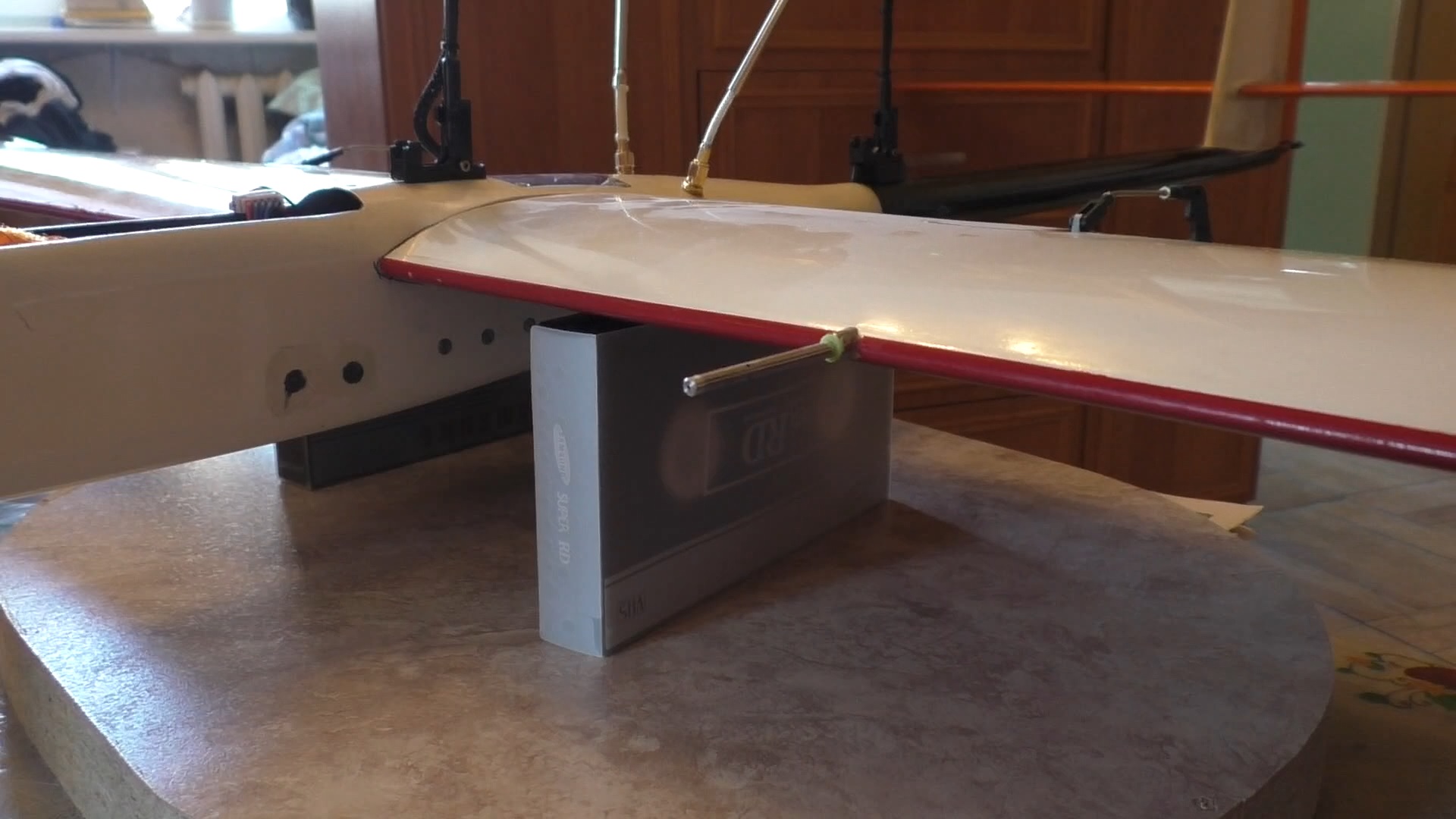
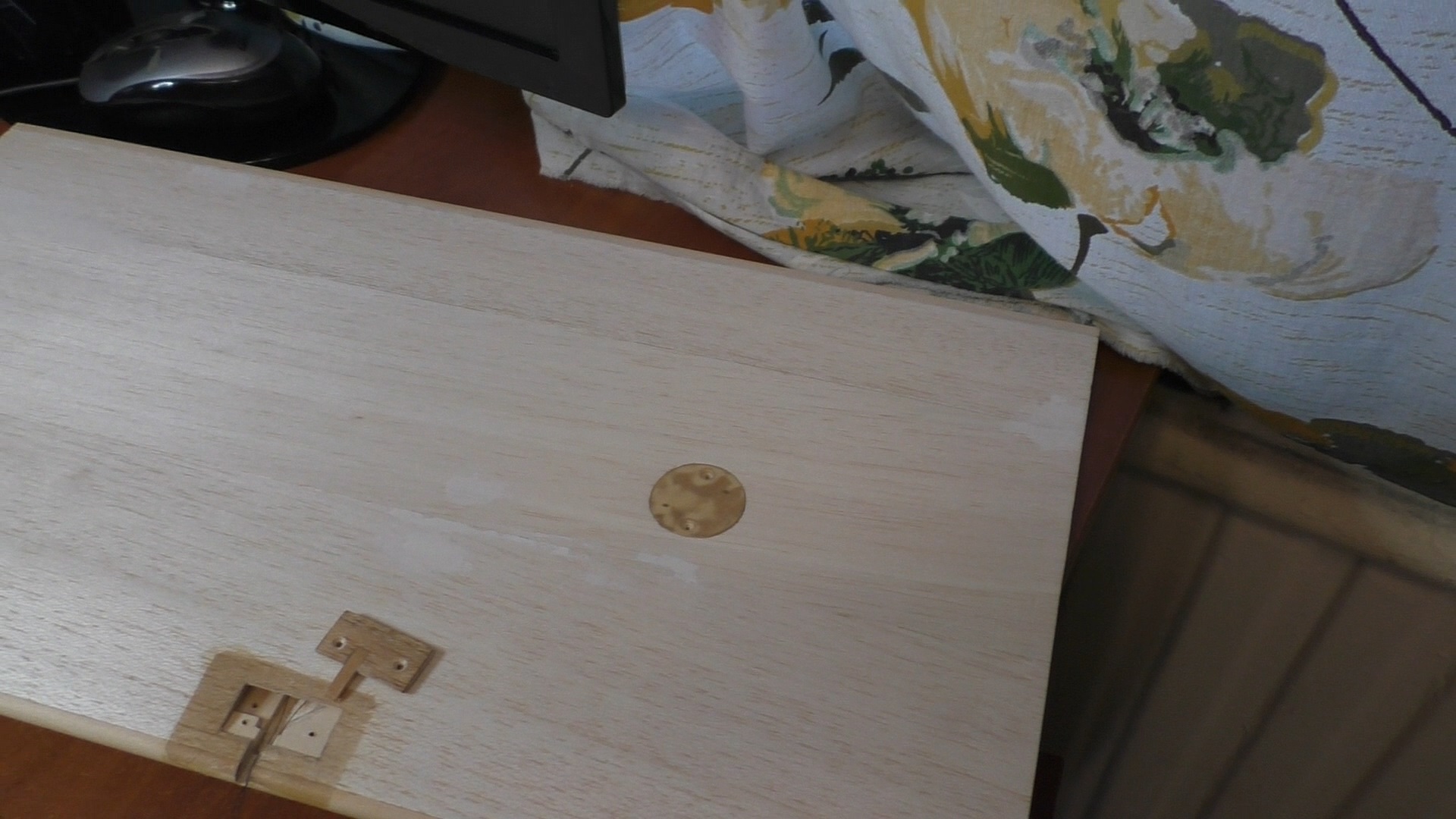
I use the Holybro 4525DO digital speed sensor. There is an I2C output interface with a limit on the length of the connecting wires. I do not exceed the optimal length of no more than 0.4 meters of wire length, but there are many sources of interference from radio waves, and there is also a reason for the convenient location in the wing of the Pitot tube, it is worth considering that when landing it can break if the tube is on the edge of the wing.
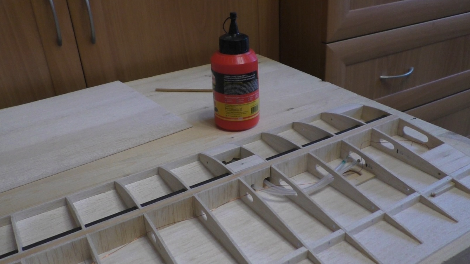
Look at my images of the wing during the manufacturing process.
I made the tube installation location convenient for installation, you can also remove the Pitot tube if necessary. The digital sensor is located under the round cover, it is available for maintenance.
I have a glider with wings of 4 meters, there is also an engine installed in the front, but it will be difficult to install a sensor on the edge of the wing. I think that the idea of installing the Pitot tube at the end of the wing will not give high measurement accuracy, as well as the installation of two Pitot tubes on different wings, the airframe flight speed is not high, so the speed difference on the wings when turning will be at the limit of the accuracy of the digital converter.
Correct reasoning can be tested on mathematical calculation and on test
I’m going to second what @Yuri_Rage said, lots of traiditional aircraft run with their pitot tubes on the wings. For the same reason: there’s an engine/prop on the nose. Works fine. I’ve built several planes with the airspeed on the wings and it was never an issue. Make sure the pitot tube sticks out far enough to get into clean air and there shouldn’t be a problem.
That’s the first time I know I2C has a wire length limit, so I can’t put the sensor to far away from the fuselage. I decide to put one sensor on one side now. I will do ground test to check if the prop airflow changes airspeed sensor value.
You can’t fly such tight turn radii that the difference in speed on the minimally different circular paths makes a relevant difference. You can calculate it.