@pilotltd may I suggest you open a new discussion on Mission Planner tag and @Michael_Oborne will look at it.
@snoozer yes a simple “termination” connector/cable can do the job
@pilotltd may I suggest you open a new discussion on Mission Planner tag and @Michael_Oborne will look at it.
@snoozer yes a simple “termination” connector/cable can do the job
My replacement TF Mini Plus arrived today. Plugged it into my pc opened the app, connected and boom data. So for sure the first one was faulty.
Dumb question @ppoirier
If these commands convert it to I2C mode.
5A 05 0A 01 6A
5A 04 11 6F
Does the device stay in UART mode till its rebooted.
Also how do you convert it back to UART
.
The first command select the I2C mode
The second saves the mode in non volatile memory
To revert to serial, you need to send the command on I2C mode, that can be done with an Arduino or from a Rasberrypi using the i2cdetect shell utility
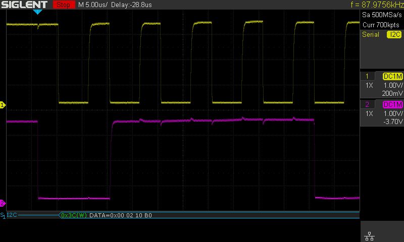
@ppoirier, thanks for the suggestions. I have hooked up a scope to the I2C port 1st with the OLED display and I had a clean clock and data signal without any external pull-up resistors. The clock measured about 87kHz. Display works perfect.
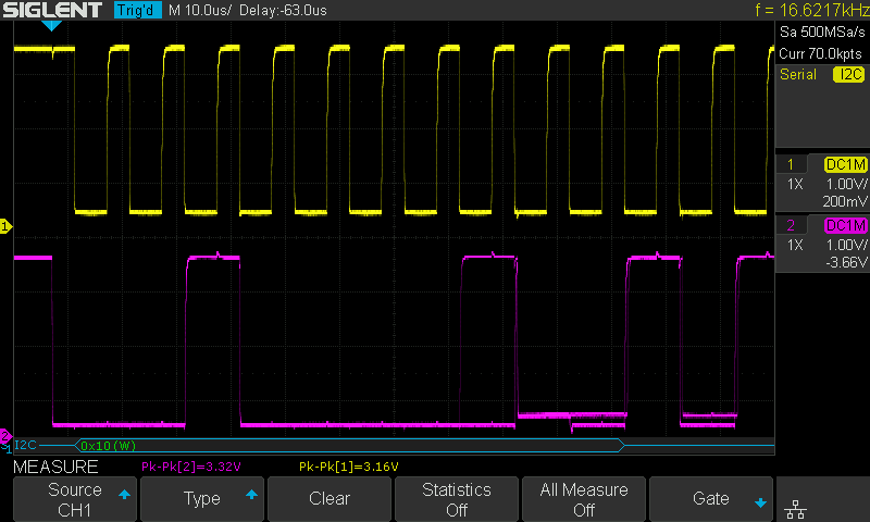
Next I reconfigured the Pixhawk 4, removed the OLED and disabled the display in the config, set the address for the TFmini S to 16 (0x10 in hex) and used type 25. I get a reading of 10cm which is WAY off and it does not change. Also the GPS goes wild and the I2C clock goes down to 16kHz. I am beginning to wonder doe I have a faulty unit ? Again the scope shows clean edges but for some reason no go and slow bus.
Regards
Jan P.
PS: I wonder do I need to set extra parameters such as “Output Format”, there are the choices 9 byte cm (default), Pixhawk, and 9 byte mm.
So I did what I was told.
I plugged the TFmini Plus into the pc and ran the gui. Unit works like a charm.
I then sent the following commands.
5A 05 0A 01 6A
5A 04 11 6F
I set the address to 16 and the type to 25 as discussed above.
All I get is rangerfinder 1 not detected. I rebooted …same.
Here are my config settings.Everything appears to be correct…but no go and now of course I cant’ test the lidar as it’s in I2C mode.This is the same unit and the same supplier that Patrick uses. Very odd
Suggestions anyone.
RNGFND_GAIN,0.8
RNGFND1_ADDR,16
RNGFND1_FUNCTION,0
RNGFND1_GNDCLEAR,34
RNGFND1_MAX_CM,600
RNGFND1_MIN_CM,30
RNGFND1_OFFSET,0
RNGFND1_ORIENT,25
RNGFND1_PIN,-1
RNGFND1_POS_X,0
RNGFND1_POS_Y,0
RNGFND1_POS_Z,0
RNGFND1_PWRRNG,0
RNGFND1_RMETRIC,1
RNGFND1_SCALING,1
RNGFND1_STOP_PIN,-1
RNGFND1_TYPE,25
@rickyg32, if you have a R-Pi or any other Linux box with I2C you could install i2c-tools and change back to UART:
To get it back from I2C to UART I issued the following on a Linux CLI:
To verify its on address 0x10:
i2cdetect -y 1
Set UART:
i2cset -y 1 0x10 0x5a 0x50 0x0a 0x00 0x69 i
Save Settings:
i2cset -y 1 0x10 0x5a 0x04 0x11 0x6f i
That worked for me when I tried the 1st time around with I2C and go back to UART. As you can see above I have no luck with I2C either on this and it is not a termination issue, something else must be configured on the TFmini S or maybe there are different firmware versions out there, some work and some don’t. Unfortunately neither Benewake nor my supplier 3DXR in the UK is responding to information requests. The Benewake Windows application is also not showing any responses when issuing commands. Very disappointing.
Regards
Jan P.
PS: The -y 1 part of the above depend on the bus number.
Hi JP.
I don’t have a Raspberry Pi. But I suppose I could get one.
IS there any documentation around on how to connect it up and what sketch you need to do all this.
A R-Pi is an actual computer, you don’t have “sketches”, you issue commands on a command line. Somewhere further up is a reference to an Arduino type device, that’s a Microcontroller board which uses a sketch to make it work. You might have to google a bit about that, I have not details on that off hand.
Re r-Pi just google “r-pi pinout” and you get plenty. GPIO 4 and 6 are +5v and GND, 3 and 5 are SDA and SCL.
Rgrds
Jan
IT still requires some form of code to run doesn’t it.
Patrick I assume for this your using an arduino Pro mini.
If so what are you using for the interface to talk to the tf mini. Is it still the Benewake Tf gui. I either need to revert mine back to UART or check the address. Tomorrow I am going to see if the external LED I have on the quad is colliding with the lidar.
But if not then I need to convert back to UART
Hello
Just to make sure, once you sent commands to switch to I2C, the signal stopped on the serial port?
And then you connect scl to scl and sda to sda ground and vcc between TFMINI and Flight Controller?
Well now that you mention it I just assumed the connector was setup for a pixhawk…its the right type of connector for an I2C hub or port.
But I think the SCL and SDA are reversed on this
This is the pixhawk I2C buss pinout
@rickyg32, may I ask what Flight Controller you use ? I am using a Holybro Pixhaw 4. I am just trying to find out what our setups have in common to not work where others seem to be working including the tests of @ppoirier.
Thanks
Jan
If that can help

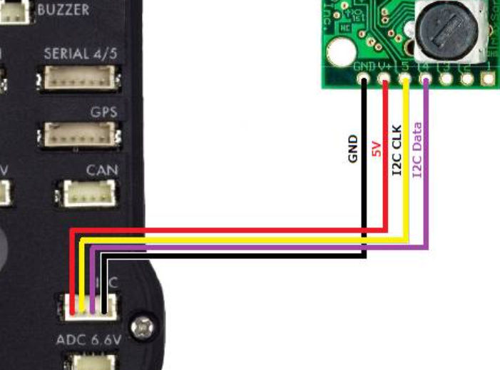
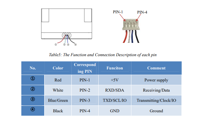
please note the green-white are criss-crossed
So here is how to get the TF Mini Plus working on Pixhawk I2C.
Connect your TF Mini via the supplied cables to a TTL to USB adapter.
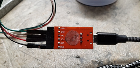
Connect via the USB cable to your PC.
If you have not already downloaded the TFMini Gui…do so from http://en.benewake.com/support
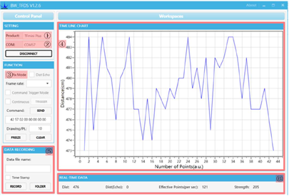
Open the Gui
You should start seeing distance information on the graph in the gui.
Using the command line function issue the following two commands by pasting each in the command line and pressing send
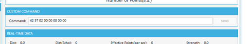
5A 05 0A 01 6A
5A 04 11 6F
The first sets the device to I2C and the second forces a save.
Nothing should appear on the graph from this point on.
Next you need to connect it to your Pixhawk or I2C hub.
Please note that the pinout on the supplied connector has the SCL and SDA reversed. You need to pull out the pins and swap them.
Please note the SCL and SDA are reversed.
You need to configure a few settings in Arducopter.
RNGFND1_ADDR,16 This is the I2C address for the Lidar
RNGFND1_GNDCLEAR,34 This the distance from the Lidar to the ground…easiest way to set it is to have the drone report the distance to the ground when sitting on your workbench and then enter that distance.
RNGFND1_MAX_CM,600 Set this as the max distance the device will be used.
RNGFND1_MIN_CM,30 This is the minimum distance for the lidar.
RNGFND1_ORIENT,25 This is telling Arducopter that the lidar is pointing down
RNGFND1_TYPE,25 This sets the lidar type to TFMini I2C
It should be working now.
Good luck
Thank you @ppoirier for all your help and patience.
I am using the Pixhawk mini in this instance. Please check the setup doc I just posted that might help. I consolidated all the information thats been provided into one spot. It works I did it this morning successfully.
Thank you both @rickyg32 and @ppoirier. I have different values for RNGFND1_GNDCLEAR, RNGFND1_MIN and RNGFND1_MAX but my values work if I use it as UART, the other values are the same. I am using the I2C A port on my Pixhawk 4. I will do some more troubleshooting on a R-Pi, I have no clue what else to try.
Regards
Jan
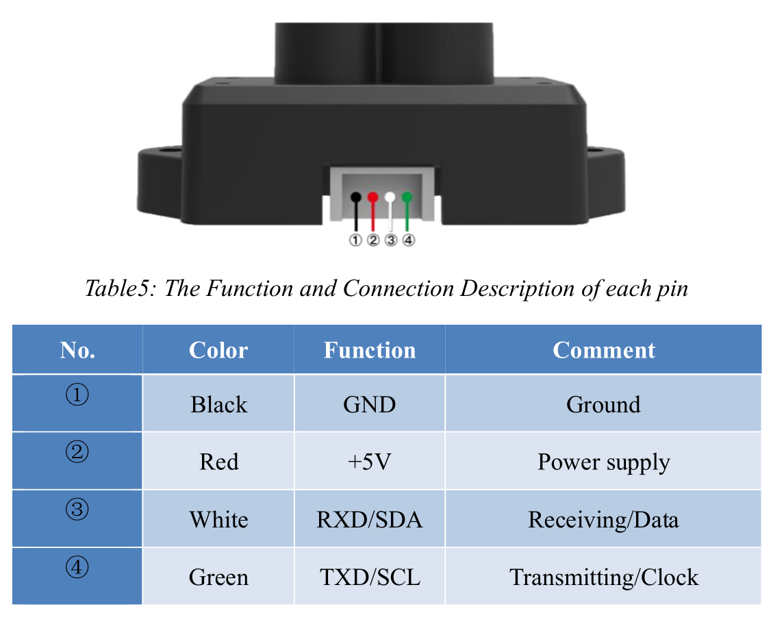
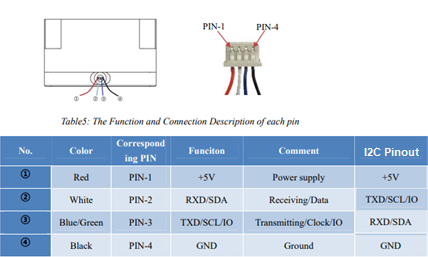
PS: Also just to mention, the TFmini S has the following pin out, I did swap the connectors around so they match up with the Pixhawk:
If you have an Arduino , you may try this
I am not a coder, I feel way more at home on a Linux CLI than an Arduino. I try the Linux approach 1st and see what happens 
Thanks
Jan
Did raise a question in Mission Planner tag - no response. Looking at the app history nothing has happened with it in years.