Well, it turns out there is no such thing as configuration mode on that TFmini-S, it work if typing the hex code do the checksum and issue the safe command. HOWEVER now I have the range finder working kind of, its VERY slow updating, WAY slower than via UART and my on board I2C display wont work any longer. If I read that right the address of the SH1106 display is either 0x3c or 0x3d, that should not have issues on the same bus. But the lidar its not really any use with one update every 30 seconds or there about. I have also noticed since the last Mission Planner update 1.3.71 it all has gone VERY VERY sluggish and updates on screen are really slow motion. Guess thats a different matter. So I am back to square one, I am hesitant what to try next now. I am tempted to get a can bus lidar hoping that works better. I see Benewake has a few of those but I can not make out if they work with Ardupilot or not.
I had it running now for a while, its very unreliable. The ranges I get vary drastically between over 100cm to 10cm in the very same location pointing at the same surface. With UART that was not the case at all. So the TFmini-S is definitely a no go for I2C on current Ardupilot. Still wondering why the Display stops working because its on a different address. Is that a general limitation on Ardupilot ?
Thanks
Jan
PS: To get it back from I2C to UART I issued the following on a Linux CLI:
To verify its on address 0x10:
i2cdetect -y 1
Set UART:
i2cset -y 1 0x10 0x5a 0x50 0x0a 0x00 0x69 i
Save Settings:
i2cset -y 1 0x10 0x5a 0x04 0x11 0x6f i
Thanks for the suggestion, I will check if I find anything that works with Ardupilot. I have only started taking an interest in Quadcopters recently. So the Holybro X500 kit was a purchase to start getting into it and see how I like it and either leave it at that or move on to something bigger or something faster. Its a learning platform for me and one thing that I got very early on is to not waste any UARTs if at all possible. So my attitude is to use a bus where ever possible (CAN bus GPS next time for example) . On this quad its also about finding out how things work together in Arducopter, what is a gimmick and what is really useful. So for the next build I have hopefully a better idea what components to use and what traps to avoid.
I consider this issue solved now since it was established that TFmini (xxx) is not the same as TFmini, so I just purchased a incompatible sensor for my use case. I would still be interested to hear if people have any suggestions how this could have an impact on other I2C devices connected to the bus.
Wa Hooo
My I2C TFMini Plus or pro what ever it’s called arrived today.
So is there some command I need to give it to have it talk I2C or is it natively talking !2C
.
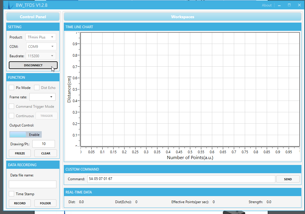
Well I connected it to teh TFMini Gui and get nothing on the screen.
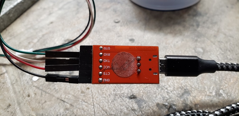
I have the TFMini connected via an TTL USB adapter as I have done many times before. But no go.
Any thoughts. I must be missing something.
when my TFmini-S arrived it was in factory default configuration which is UART, mine worked straight away in that mode and I had immediately the distance read out as graph in the GUI. If yours is set to I2C from the supplier then you wont be able to talk to it with UART. IDK how to talk to it via I2C in Windows. I have used a R-Pi and the Linux CLI. You can connect the Lidar to the GPIO header. The manual for your device should contain a pin out. If you google R-Pi pin out you will find plenty to go by, Just connect +5v, GND. On the R-Pi pin 4 and 6 for example, I2C is on pin 3 and 5, SDA and SCL. You need to install i2c-tools, that will provide i2cdetect and i2cset. You have to enable the I2C interface for example with rasrpi-config -> interfacing options -> i2c. The TFmini-S is by default on address 0x10, IDK how that is with the device you have. With i2cdetect you should see the address show up in the output.
I have learned with my experience that there is a difference with TFmini and TFmini X devices. So I guess you have to know the exact model to find out what is going on.
I am totally new to Lidars, so I can only speak from my very limited experience.
Regards
Jan P.
PS: IF it is indeed a UART device or configured for UART, watch out for the wiring RX <-> TX and TX <-> RX, otherwise you see nothing.
Hi Jan Paulini
I have the TFmini Plus. I have quadruple checked the wiring. IT appears to be connected correctly yet no output. Also I note that in the manual it indicates the default output is UART.
I can see that the device is working as the red led is lit. I am going to bung it into an I2C port and see if for what ever reason it’s set to I2C and not UART. Apart from that I am stumped.
I am kind of unsure how I shall proceed myself TBH re Lidar. I have been looking for affordable devices and only Benewake is coming up. I know now the TFmini-S I2C is not working for sure, Looking at the TF03 which is available as CAN bus model, Ardupilot does not state which TF03 models are supported as RNGFND?_TYPE. Value 27 BenewakeTF03. Its puzzling to me why a manufacturer has so many different protocols…
@rickyg32, you don’t have any other hardware to test the adapter ? From experience they need some tough handling to break. Maybe an Arduino or something ?
Not sure how to test it another way.
I agree that it takes a lot to break them. They are cheap enough so I ordered a couple just to be safe.
It’s clear from the gui it see’s no data
Had the same problem and it has been reported elsewhere. Advice from supplier was forget I2C - there have been reports of slow updating and other problems. Use a serial port. I put mine on GPS2 port as my GPS uses CAN and Telem1 and Telem2 are both in use on my system. Works fine on serial.
I am using the FMU debug port now, the other UARTs are all busy. I am still puzzled that the I2C display stopped working and I am getting nowhere to get any solid information about other I2C or CAN bus Lidar. The TF03 is also available as CAN version but I cant find any confirmation that it works in Ardupilot.
I forgot - the other recommendation was use an external 5V supply from Bec or some other device if you have a lot of items running off the Cube’s internal 5V supply or you can get drop outs, or simply failure to work. The TF02 is allegedly I2C or UART, but uses the same rubbish utility program and commands as all the other Benewake offerings and I wouldn’t risk good money on one. There are the LightWare ones, but they are expensive but allegedly work, with a caveat that use serial if cable run is long - whatever long means…